Water Power

Run your car or bakkie on water with a HHO or HHOO generator.
![]()
![]()
![]()
![]()
![]()

You may e-mail me at
john@hydroxypower.co.za with questions, suggestions or if you
can help in any way.
|
Water Power
Run your car or bakkie on water with a HHO or HHOO generator.
|
|
How to build a basic hydrogen-on-demand wet cell. Keep it green with organic Septic Tank and Pit Latrine Treatments
|
1 June 2010 I checked my consumption today. I have traveled 264,5km (all town driving) with the aircon on all the time and the consumption was 11,4km per liter. The usual consumption for town driving (and aircon on) without the electrolyser running is 10km/l and on a good day 11km/l. The improved consumption (although small) means that I am closer than before to that elusive "sweet spot". Previously with my best efforts I could only equal the consumption that I normally get without the electrolyser running. The ammeter reading on cold start varies from 11A to 13A. After it has run for a while the amperage goes up to 15A and the temperature of the electrolyte is barely warm to the touch (I guess <25°c). I must check the gas output again but I recon that it is still under 500ml per minute. The improvement in fuel economy is a step in the right direction for 2 reasons: less fuel used (less money spent) and less pollution into the atmosphere. Bakgat! BUT... still not good enough. I am still looking for a much greater improvement. Try, try, try again.... 2 June 2010 I have just seen something interesting on a commercial website selling dry cells. These work on the same principle as the one that I want to build in that the gas and electrolyte are both expelled via the same outlets upward to the reservoir. They also have 2 outlets at the top of the unit for the outflow. The difference is that theirs have 2 return inlets on either side of the bottom of the unit, whereas my design catered for only one inlet at the bottom. It makes sense to have 2 return lines if there are 2 outlets. These cells are also designed so that the plates extend beyond the seals/spacers for any heat to easily dissipate. The outside of these plates then essentially act as cooling fins. I like this design, so I have changed my design accordingly. The ss plates and the perspex end pieces have already been ordered, so I can't change those dimensions. So I will sacrifice the active surface area in order to bring the spacers inwards by 10mm all round. This will then expose 10mm on each of the 4 sides of each plate for assisted cooling. Bakgat! I have also decided to increase the size of the holes through the plates, which allow circulation of the electrolyte and gas, from 8mm to 10mm. Since I can't find any barbed/threaded elbow fitting combinations which take an 8mm id tube, I have decided to use the available 15mm fittings. I feel better for the increased diameter because 15mm id tubing between the electrolyser and the reservoir will be far less restrictive to the gas/electrolyte flow than the 8mm id tubing that I originally planned on using. The tubing for the gas feed from the reservoir to the scrubbers and to the intake manifold will still remain 8mm id. Hopefully the ss plates and the end plates will arrive this week... 3 June 2010 The perspex plates have now arrived, I just need to collect them. The 10mm thickness differs vastly in price to the previous quote I got on 16mm. The total of both plates is now only R139,00. Still waiting for the SS plates though... Here is the schematic for my revised design. I decided to reduce the size (diameter) of the threaded rod, which holds the whole shebang together, to 6mm. There will be a broad fender washer and a spring washer used in conjunction with the nut on the end of each rod. Each rod will have a length of clear plastic tubing over it to prevent accidental contact with the plates, so as to prevent a short circuit. I will also stagger the holes through the ss plates to minimise current leakage.
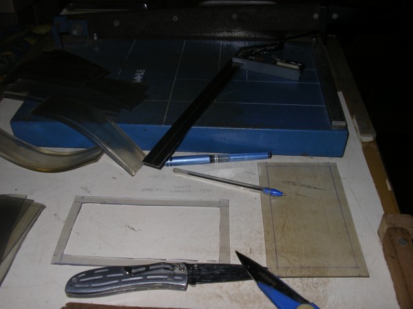
6 June 2010 I cut the spacers for the dry cell with the help of a guillotine for the outside cuts. This made the job fairly easy and quick. I used a sharp knife and scissors to cut out the inside section.
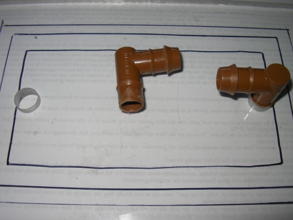
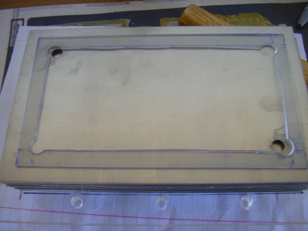
I have collected the perspex plates. I marked them to show where the spacers and the plates would sit. Originally I was going to use 15mm elbow fittings, which are barbed on one end and threaded on the other end, for the gas out and electrolyte return. I took these to an engineering shop and asked if they would be able to tap a thread into perspex for these elbow fittings. They said that they could not quite match the thread but the problem was that the threaded section was also tapered. Furthermore each tapped hole would cost me R20,00! 'n Boer maak 'n plan. I found another type of elbow fitting which was barbed at both ends. I ground the one barb (or ridge) off the one end and also shortened the length of that end. I then drilled holes in the perspex to receive these fittings, about 14mm diameter.
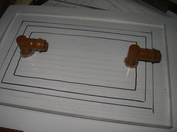
I used quick-set epoxy to glue the fittings in the holes. The fittings don't protrude out the other side of the perspex.
I will wait until the stainless steel plates arrive before I drill the holes in the perspex for the threaded rod. I have decided to err on the side of caution with the gas-out and electrolyte-in fittings. My original intention was to have inlets and outlets on both perspex plates. For now I will only have these on the one plate. I might order another perspex plate and mount similar fittings on that one, and then swap them to see which is the better set-up, i.e. 2 x outlets and 2 x inlets versus a single outlet and inlet. Instead of silver soldering the cable onto the 3 active plates, I have decided to rather ask the guys at the engineering works to weld tabs onto these plates. These tabs will be drilled so that connectors can rather be bolted on.
I have been scouting around for a suitable reservoir. I have in mind a radiator water reservoir as these are robust and they can take heat and pressure. Our local scrap yards so far have only yielded very small ones which in my opinion will hold an insufficient amount of electrolyte. Furthermore the scrap yard owners are all asking R150,00 for these small reservoirs! Very second hand nogal! We will be traveling to Jozi for a few days next week on business. I hope to have my new dry cell completed and fitted before then. If not, I will continue to run the present wet cell. Even if my fuel economy is the same as I usually get without the electrolyser (which is normally very good), I will be happy because at least the exhaust will be spewing less harmful emissions and the engine will also benefit. The past few days have started off cold (± 15°c) and consequently the amperage on start-up in the mornings has been around 10A. After a while it eventually settles around 15A. All indications are that I am still getting slightly better fuel economy than before without the introduction of HHOO into the engine. 15 June 2010 Well, after just over 2 000 kilometres I am sad to say that my best results were obtained without the electrolyser running. Having said that, I ran it only on the up run and for a while in and around Jozi where traffic and other factor were not conducive to good fuel economy. After running for about 2 hours, or if the weather was warm, then the amperage would climb past 15A. With the increase in amperage the electrolyser would also be putting out a higher volume of HHOO. Between 18A and 20A I would switch the electrolyser off as I know that the increased hydroxy is counter productive because of the MAP sensor. The first leg of our journey from Port Shepstone to Harrismith gave a result of 13,93km/l with the electrolyser on all the way. Three days later after a lot of running around on the highveld I got 13,55km/l. This second leg was with the electrolyser on only part of the time as explained above. The third leg from Jozi to Harrismith gave me 15,24km/l - without the electrolyser. I have not measured the last leg home but I expect it to be similar to the previous one. So, even with the "less is better" principle The MAP sensor is still mitigating against good fuel economy. Nou ja... I am still waiting for the stainless steel plates that I ordered for my new dry cell, can you believe it?!! Ja boet... 25 June 2010 Hard to believe, but my plates have eventually arrived! But then they told me that they could not weld the tabs on the active plates as they were too thin (0,9mm) and would warp drastically. Oh well, plan B. I will cut the corners off the plates on either side of the active plates in order to give a bit more space for a bolt and nut connector for the power cable.
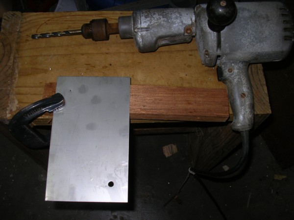
I got to work drilling holes in the plates for the through flow of gas and electrolyte. This is my second hole that I tried drilling with a 10mm bit. I used a drilling machine that is geared to operate at a slow number of revolutions and with olive oil as the lubricant. But the bit was not a good one!
I then decided to use a bit that is especially meant for stainless steel - much happiness! Although it is only 8mm I will see if these size holes are sufficient for the flow/circulation of gas /electrolyte.
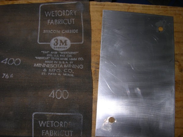
I found an abrasive gauze amongst my late father-in-law's tools. It is probably 30+ years old. It is not very coarse/ abrasive but it is sufficient to at least give the plates a matt or brushed-looking finish. I thought I'd try the roughing up thing for greater gas production. My effort is weak, I know, but this is better than nothing.
I finished drilling the plates, sanding them, and then I scrubbed them down with pine gel to get rid of the finger marks and olive oil. This is when I remembered that I must still drill the holes in the corners of the active plates for the terminals, and cut the corners of the flanking plates. It was also at this time that I saw that I had left one plate behind, but is too late to go back to the garage tonight (it is now early morning actually) so I'll carry on tomorrow (later today!). I must now buy the ss threaded rod, nuts and washers to hold the stack together. Also, I still need to drill the holes for the threaded rod through the perspex end plates. I am still looking for a suitable container as the reservoir. I will scour the scrap yards again... Môre is nog 'n dag... I drilled 6.5 mm holes in the perspex end plates for the 6mm threaded rods. For some reason I really battled with drilling them. I clamped the 2 perspex plates together and I used my drill press for the job. The bit would bite vas every time just as it cleared the second plate. Yet when drilling large holes it was plain sailing and neat.
I used my homemade punch to round the corners of the insulators so that the flow of gas/electrolyte would not be hindered.
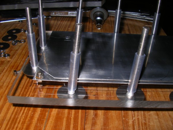
Checking the stack to see if the holes line up.
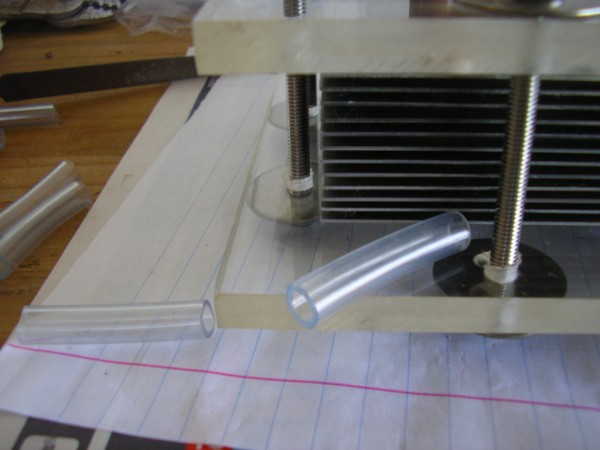
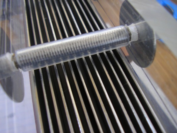
Here it is coming together. The tubing is to insulate the threaded rods.
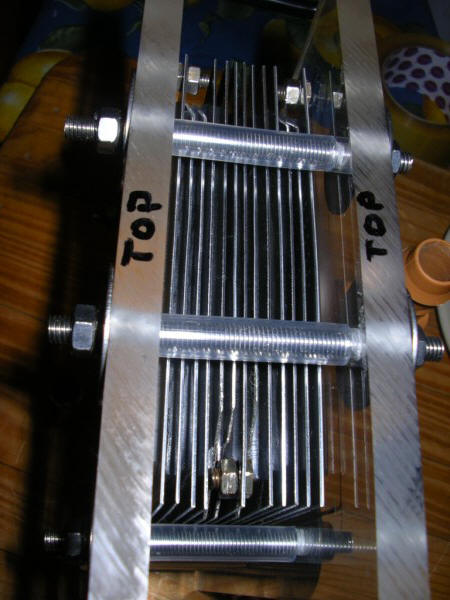
These worked out very well. On the ends of the threaded rods are a nut, spring washer and a 32mm fender washer (all stainless).
I thought it looked good, but when I finished it I noticed 2 problems:
1. The inlet and outlet are on the same side of the cell which may be counterproductive to gas production and the flow through the cell.. 2. I also forgot to make provision to connect the cables on to the active plates! The 5mm bolts that I had in mind will clearly not fit.
I pulled the cell apart and epoxied a 5mm piece of perspex over the inside of the lower inlet hole so that this end plate would only have an outlet for gas/electrolyte (at the top end of the plate). I drilled another hole at the bottom of the other end plate so that the inlet or return for the electrolyte will be on the opposite end of the cell. I also cut the corners off the plates adjacent to the active plates so that the connector bolts would not make contact with the neutral plates. I also cut the bolts shorter and I ground the heads down.
The re-assembled cell.
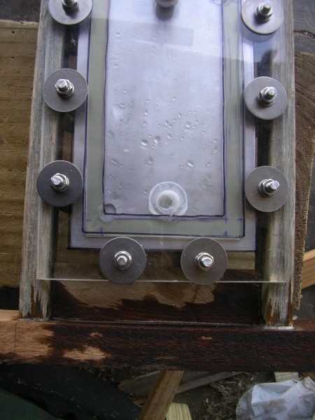
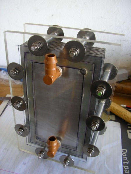
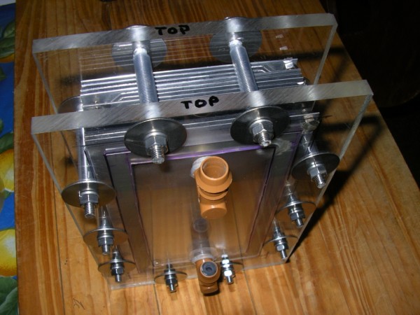
Because the connector bolts on the active plates cannot be removed without pulling the cell apart, I will use open lug connectors on the ends of the power cables. I also don't have enough spring washers for these connections so I will secure them with a drop of super glue. The finished product. I am quite proud of my first attempt at building a dry cell, notwithstanding the occasional hiccup! The brown fitting at the bottom is for the electrolyte return.
I put a plug in the bottom fitting as the hole in through the perspex is now sealed. The top fitting is for the gas/electrolyte to exit to the reservoir.
If the single exit and return is sufficient in that the flow of gas and electrolyte is not hindered, then I will order another perspex plate and redo the above one so that it only has a single fitting on this side. If I find that 2 outlets and 2 inlets are required in order to ease any restriction on the electrolyte and gas flow then I will proceed with my original plan and open the closed bottom fitting for the second inflow (of electrolyte) and fit another fitting on the other side for the second out flow (gas and electrolyte). Next step is to test this cell and to run the plates in. In the meantime I will continue to look for a suitable reservoir. 29 June 2010 I have still not found a suitable reservoir so I've decided to try the fridge water bottle which presently serves as the first scrubber on my old wet cell. I made a frame to hold the reservoir above the cell.
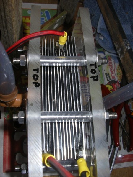
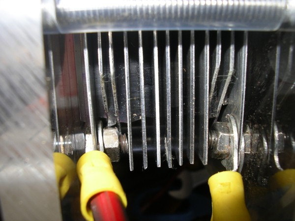
The cell rests on a thin piece of wood on the bottom bolts. This allows air to flow freely over the end of the exposed edges of the plates for cooling.
I decided that the HHOO outlet should be through the lid as it is the highest point on the reservoir. After drilling the hole I sized the fitting in by heating it with the heat gun. Although it turns in nice and tight I ensured a good seal with some pratleys.
I secured the fitting on the inside of the lid with a plastic disting.
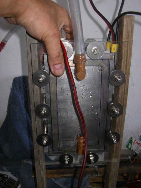
The assembled article. The electrolyte return fitting has a tube connected to it on the inside of the water bottle which reaches to the bottom of the bottle.
I fitted connectors onto the active plates before I remembered to take some photos. I bought 3 lug connectors and I cut the ends open. Later on I will have to remove the reservoir in order to connect the power cables to the connectors.
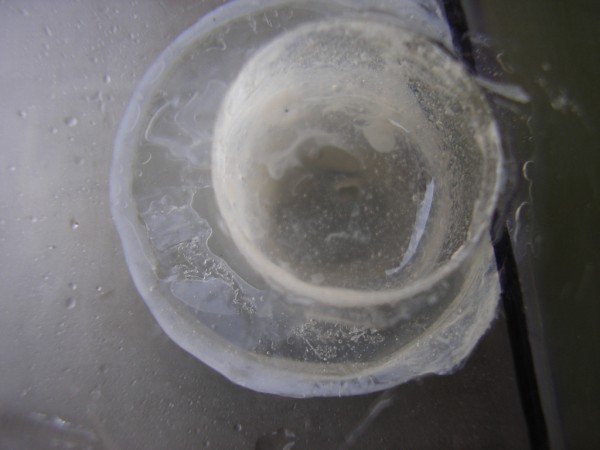
Initially I'll connect it up to the existing cables in the car and run it there to see the true results - my bench power supply puts out less than 13,8v and it also cannot handle many amps. Môre is nog 'n dag... 30 June 2010 I set the cell up to run off my bench-top (computer) power supply while my wife was in town with the car. The cell leaked at the bottom end and even when I tightened the nuts the leak persisted. I then discovered that the leak was coming from the plug I pratleyed in the perspex end plate. I removed the plastic elbow (which was not being used). I left the perspex plate on the inside of the end plate and just applied more pratleys in the recess and let it dry.
A closer view. This provided a good seal.
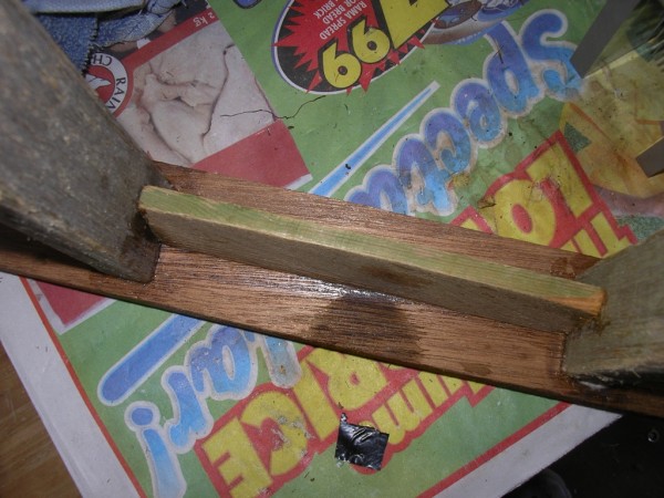
Since I had to unassemble the contraption I used the opportunity to take more photos. Here is the support for the cell at the bottom of the frame.
The connectors attached to the active plates (+ - +).
A closer view. The bolts and nuts are not touching the other (neutral) plates - it just looks like they are.
Sliding the cell assembly into the frame.
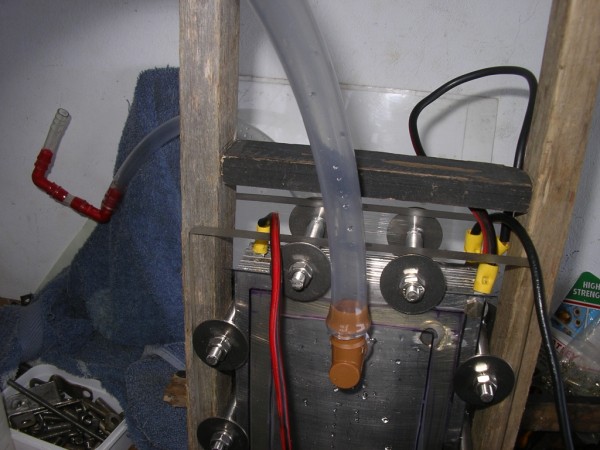
The support for the reservoir screwed in place.
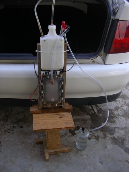
The reservoir is in place and ready for bench testing. I ran it for a short while and then the power supply packed up - the KOH concentration was too much which resulted in too high an amperage. I never had the opportunity to put my multi meter in-line to test the amperage before it popped. When my wife returned I connected the cell up to the existing power cables in the car (there from the previous wet cell installation).
I found that the gas was only partially venting out to the bubbler. The circulation of the electrolyte (which was supposed to be via the reservoir) was not happening. Reason? The vent return to the cell must be at the bottom of the reservoir so that the return flow is as a result of gravitational forces! Even though the vent tube reached all the way to the bottom of the reservoir, the electrolyte will not be forced up and out as the pressure is negated by the gas venting to the scrubber! Nou ja... I will have to get another fridge bottle (or other suitable container) and re-do the reservoir. I briefly ran the cell after bypassing the reservoir and it was exciting to see the action at 20A. Measured production was only 700ml per minute but since the plates have not been run in etc. this is not a true reflection of the cell's potential. I need to acquire another bench top power supply in order to run the plates in properly. |
|
The information presented on this website is for you to look at, learn from, laugh at, or whatever. But if you try anything that you see here it is at your own risk. I will not take responsibility for your stupidity should something go wrong. |

.jpg)
.jpg)

.jpg)
.jpg)
.jpg)
.jpg)
.jpg)
.jpg)
.jpg)
.jpg)