Water Power

Run your car or bakkie on water with a HHO or HHOO generator.
![]()
![]()
![]()
![]()

You may e-mail me at
john@hydroxypower.co.za with questions, suggestions or if you
can help in any way.
|
Water Power
Run your car or bakkie on water with a HHO or HHOO generator.
|
|
How to build a basic hydrogen-on-demand wet cell. Keep it green with organic Septic Tank and Pit Latrine Treatments
|
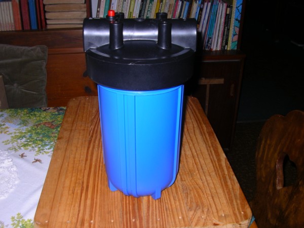
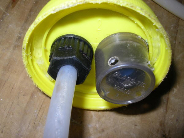
CELL DESIGN For anyone wanting to build a basic HOD (Hydrogen on demand) brute force cell, there are many "free" plans on the internet. There are some dangerous designs such as those in glass jars. These have wire anodes and cathodes which I'm sorry to say cannot produce enough hydroxy to power a dinky toy. DON'T TRY THIS DESIGN! You WILL be wasting your time and money. The "designer" of this glass jar design also advocates the use of a one-way valve on top of the cell to "allow air in when there is too much vacuum" in the cell. There is NEVER a vacuum inside the cell unless you have a strong air pump sucking the gas out of the cell, so this "innovation" is superferlous. There are 2 primary types of cells that can be built by the "do-it-yourself" person: the dry cell and the wet cell. The dry cell requires more finesse but it is regarded as more efficient. The wet cell is easier to build for the average tinkerer and it requires less expertise. For the purpose of this discussion I will focus on how to build a wet cell. The Housing The basic requirements for the housing are: 1. It must seal air-tight. Hydrogen has a smaller molecule than most other gasses and a water-tight seal does not mean that it's "air" tight. A leaking cell is the greatest contributor to failure and frustration. 2. It must be able to withstand heat. The type of material that the housing is made of is very important and so is the thickness of the container. Although the plates and the electrolyte may not get too hot, the heat can build up on the connecters where they meet the plates and also where the positive and negative wires are connected to them. Excessive heat in this region is as a result of either the wires and/or the connectors being too thin for the amount of current (amperage) generated by the cell, or as a result of loose connections. I have always gone for "overkill" in terms of the thickness of wires (3 - 4mm) and connectors (8mm bolts/threaded rod and 8mm nuts and washers). All my heating problems (with connectors) has always been because of loose contacts (nuts which are not tight enough). If the housing material cannot take much heat and/or it is too thin, then the points where the connectors pass through the housing can either melt or become soft enough to allow gas and/or electrolyte to escape. The areas where the cell seals can also become vulnerable to leaks either as a result of heat or perhaps because the mechanical seal is not too good. 3. It must be able to withstand the knocks. Any container that cracks or breaks easily is not suited for this project. Unavoidably the suitability and robustness of containers relates directly to cost. The most successful container that I have tried so far is the water filter canister.
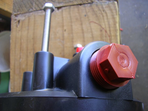
The lid already has 4 well placed tapped holes that are easy to drill through. The 2 holes on either side of the lid are easily plugged by end plugs readily obtainable from any store or co-op that sells agricultural supplies.
Location The location of the cell will to a certain extent also determine the type or shape or size of the cell housing. I have tried many different housings because of limited space in the engine compartment. My present cell (housed in the canister above) is situated in the boot where size is not really an issue. The Cell Plates Cost is a primary consideration with regards to the materials that are selected for the plates. Stainless steel is most favoured for its availability and it can be reasonably "worked" at home. The higher the grade of stainless, the more the cost and it becomes more difficult to work with as it is harder. But with the higher grades there is less gunk (carbon, etc.) given off in the electrolyte, and it is generally accepted that the yield of gas is better. Grades: I have used 304 grade extensively in my experiments as it was the cheapest (and sometimes free!) available to me. I have lately been using a grade of 316 (the poorest grade in this range) which is definitely much harder to drill and cut. I order my plates pre-cut to size and then I only have to drill them. It is essential to use the correct bit and to lubricate with oil while drilling. Size: the size of the plates are dictated primarily by the container that the cell will be housed in. If you have a large container then it is important to limit the size of the plates because this will also determine the amp draw. I am presently using 403 grade plates 120mm x 200mm x 0.9mm. Why this size? Because a lot of expert use similar size plates and I also like them because they fit into the housing. I cut out a 25mm x 25mm square out of the top corner of each plate and drill an 8mm hole in the opposite corner. I also drill 2 x 6mm holes further down for the plastic/nylon bolts which hold the plate assembly together.
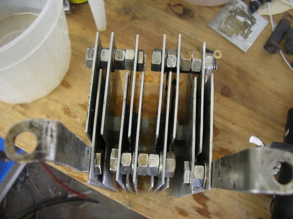
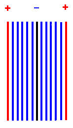
Electrolyte Much trial and error has also taught me that in the long run Potassium Hydroxide (KOH) makes the best electrolyte, which is also a universal conclusion. Sodium Hydroxide (NaoH) is second best. If you have neither of these and you absolutely have to test a cell with something, then use Bicarbonate of Soda (Bicarb). Depending on the amps drawn and other factors, Bicarb will result in the plates quickly discolouring. I use ordinary tap water to mix the KOH in simply because distilled water is too expensive. I have tried rain water, but for the amount of effort to collect and filter it, it has not proved to result in any significant increase in gas production nor that much less gunk in the electrolyte. If I were more focused on precise results I suppose I would be able to measure some gains. The amperage that the cell will draw can be regulated by the concentration of the electrolyte. This in turn will be affected by the number of neutral plates used in the design: the more neutral plates between the active plates, the more electrolyte required to produce the same number of amps. Design The spacing, number and arrangement (configuration) of the plates: positive, negative and neutrals are of paramount importance. Neutral plates are required to stabilise the current draw (in conjunction with the concentration of electrolyte) and it controls the rate at which the cell heats up. Spacing: It is generally accepted that the spacing between the interactive cells must be between 1,5mm to 3mm. Each design (plate configuration) will result in different results as far as gas generation and heat generation is concerned. The spacing in my cells are determined by the thickness of the washers (plastic/nylon and stainless steel) and the nuts (13mm for 8mm bolts/threaded rod) that I use. My washers are about 1,5mm thick and in the design configuration that I use this spacing results in the most gas. Gas: It is also important to decide what you want to produce: HHO or HHOO. Now, to the debunkers out there: thousands of cell builders run more negative plates to generate more hydrogen than oxygen. These are generally the guys who try to supplement the petrol with hydrogen as a fuel. Using the same principle, I prefer to run more positive plates to generate more oxygen than hydrogen to improve the burn of the petrol in the engine. You can generate HHOO: not from a single H²O molecule, but from 2 x H²O molecules. That is my opinion and I'm sticking to it! Configuration: A simple and effective configuration is + n n n n n - n n n n n +. Experiment with spacing these 1,5mm to 3mm apart (it will also impact on the size of the housing required) to see what works for you. This is the configuration that I am experimenting with in my dry cell.
However in my wet cell I prefer to follow Bryan Martin's design as far as staggering and connecting of the plates are concerned. This is the 12 plate configuration that I am running in the wet cell in my car right now (April 2011). See the photos above.
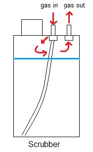
There are scientific ways of calculating the number of active (+ and -) and neutral (n) plates and also the size of these plates, to determine the optimum amperage etc. I do not go into it and anyone wanting more information on "how to" must visit the HHO forums. Controlling the amperage A good design and configuration goes a long way to keep the amperage from running away too quickly. I have tried various cooling systems to control the heat run-away in the electrolyte, some with greater success than others. Ideally a stainless steel radiator with a cooling fan should do the job - depending on the climate of course. Many experimenters are resorting to Pulse Width Modulation controllers to keep the amperage from running away. I was blessed when Sean from Centurion contacted me and offered to build me one (I can not do it as I am electronically challenged!). So far the prototype is working very well for me. Protecting the engine To prevent any electrolyte and impurities getting into the engine, it is necessary to install a scrubber (also called a bubbler). Connect this in the gas line before the engine entry point. This item can also: 1. by visual indication (bubbling action) indicate that there is gas being produced i.e. everything is connected up correctly, and that a relay has not tripped, and 2. test whether there are any leaks in the cell (housing) or the gas pipe connections up to the scrubber. When the gas-out is placed under pressure the gas will then vent through any weak spot, should one exist.
The scrubber should be at least 300mm tall and should contain at least 500ml of water. Ordinary tap water is okay. It is easy to monitor the level of water and to observe the electrolyser's performance if the scrubber is see-through plastic. As stated above, the scrubber will also show if the system is leaking gas anywhere because the water pressure at the tube end where the gas escapes into the water at the bottom of the scrubber will put enough back-pressure to force the gas to vent through any weak spots. If there is a leak there will be no bubbling action. I advocate either 2 scrubbers or a scrubber and another additional safety measure to prevent too much water vapour or any electrolyte getting into the engine. I utilise a water/vapour trap as a secondary measure. It is simple to make: the inlet has a tube to the bottom of the container and the gas then filters upwards through 2 foam rubber discs before venting through the gas-out fitting.
As an additional safety feature I have also placed the gas inoculation point under the air filter so that the gas has to travel upwards to enter the intake manifold (aided by some vacuum from the intake manifold). Any water/electrolyte that makes it this far will simply drip into the bottom of the air filter housing where it will simply drain away through the drainage holes in the bottom of this housing. Anti-splash guards It is important to also install anti-splash guards at the gas-out points in the electrolyser as well as in the bubbler. This will help prevent or minimise unwanted spillage or leakage of electrolyte or water into the gas pipes should you hit a bump in the road.
Putting the electrical system together: The basic wiring schematic:
Here is how the whole shebang is put together if you have a PWM (schematic courtesy of Zero).
This is how I have connected my PWM but it still works through the fuel pump so only when the engine is running can any power be switched to the cell. |
|
The information presented on this website is for you to look at, learn from, laugh at, or whatever. But if you try anything that you see here it is at your own risk. I will not take responsibility for your stupidity should something go wrong. |
.jpg)
.jpg)

%20(415%20x%20295).JPG)