Water Power

Run your car or bakkie on water with a HHO or HHOO generator.
![]()
![]()
![]()
![]()
![]()

You may e-mail me at
john@hydroxypower.co.za with questions, suggestions or if you
can help in any way.
|
Water Power
Run your car or bakkie on water with a HHO or HHOO generator.
|
|
How to build a basic hydrogen-on-demand wet cell. Keep it green with organic Septic Tank and Pit Latrine Treatments
|
20 May 2010 I still have not sorted out the MAP sensor - I need to find a mechanic/technician who knows what he is talking about. DRY CELL In the meantime I have experimented with a crude dry cell to see if I could get an idea of how much more efficient they are compared to wet cells. A wet cell is one where the plate assembly is immersed in the electrolyte. A dry cell is one where the edges of the plate assembly is sealed off which forces the current to pass through the plates rather than jump from edge to edge. I used some old 304 ss plates that I previously conducted other experiments with, so they all had 2 or more holes in them.
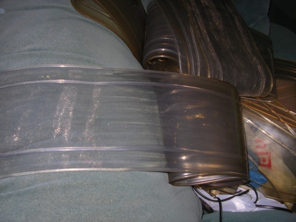
I was given some old strips of insulating vinyl from a local supermarket (thank you Mike) and I used this to make the spacers.
I cut out the center section which is about 2mm thick and 120mm wide.
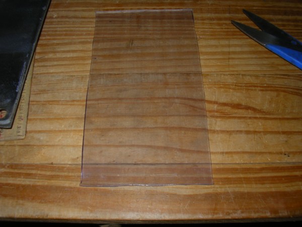
Next I cut out the center to make a gasket 10mm wide. These were a pain in the gaai to cut using only a pair of scissors and a sharp pocket knife!
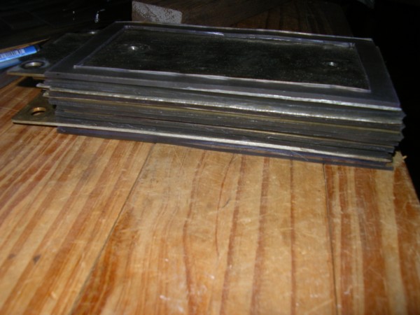
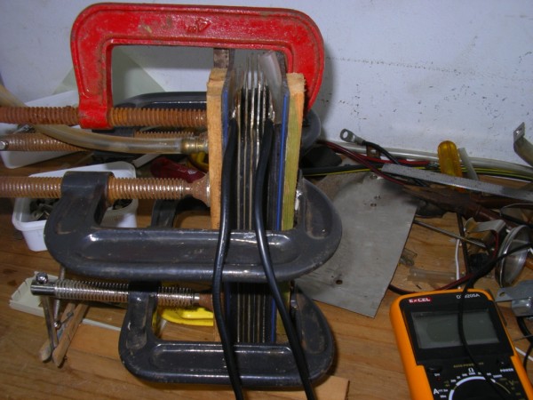
Next I put the stack together. There are 6 plates + n n n n -.
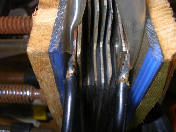
I used the perspex from an old number plate to make the end pieces. Instead of drilling holes all around the edges and putting bolts through, I decided to use G clamps to hold it together. Crude, but effective. Most important it doesn't leak. The brass fitting I heated up with my trusty "hair dryer" and turned it into a hole which I drilled in the perspex. I used Pratley's to ensure a good seal.
Can you tell I live at the coast? It doesn't matter how much you oil your equipment, the south coast cancer still gets in! A close-up showing the perspex ends. I jammed the terminal connectors onto the end plates with pieces of tubing. I put a double spacer between the end plates and the perspex.
The active surface of the 6 plates is only ± 80mm x 80mm per side. There is more available but I only filled up with enough electrolyte to cover this area. I ran the electrolyser for 2 hours with the following end results: Amperage: 2,1A Voltage: 10,4V (this is from an old pc power supply) Temperature: 40°c (after 2 hours) Production: 150ml per minute Notwithstanding the poor quality plates and that there would be some current leakage because of the number of odd random holes in each plate, I am convinced that a dry cell is the way to go. In my mind I thought that the required concentration of electrolyte (I use Potassium Hydroxide) would be less for a dry cell. To my surprise I had to make quite a strong concentration before there was any significant bubble activity. This experiment has encouraged me to continue building a dry cell. I previously downloaded a great but simple design for a dry cell with an auto fill system. Unfortunately the viruses that I had (Windows Vista and Windows 7) resulted in me losing EVERYTHING off my hard drive. Luckily I remember the basics. The most expensive part of building this cell will be the perspex. Can you believe it the last quote I got for a piece 260mm x 180mm x 16mm thick will cost R135,00! 2 ends will cost R270,00 whereas I expect to pay about R240,00 for 12 x 316 ss plates 120mm x 200mm x 0,9mm thick. I am still trying to source plastic or preferably nylon fittings for the gas and electrolyte out/refill. I am looking for elbows which are threaded on one end and barbed on the other end to take a pvc tube with an inner diameter of 8mm. The smallest that I have found (and only in plastic) is a fitting that will take a tube with id 15mm. I have asked a number of local hardware stores to try source these for me, to no avail. I am also looking for an alternative to stainless steel for the cell plates. I have taken note of the warnings that others have posted on the net regarding hexavalent chromium. Unfortunately the alternative is very expensive (titanium, etc). 24 May 2010 With the recent fuel hikes (which I predicted would come) I have decided to try another route to get the HHOO to improve my consumption. I still have had no joy with the MAP sensor so in the interim I am going with "less is better". The HHOO output is 350ml per minute at 15A. When the system warms up the output as well as the amperage should rise. I'll monitor it for about a day and then adjust the electrolyte concentration so that the output is 500ml per minute from a cold start. For the first time in yonks I had a critical look at my setup and found that the second scrubber had a leak. I removed it and applied some glue to the lid. While I am waiting for it to dry, I connected the gas tube coming from the electrolyser directly to the tube feeding the engine. I have one scrubber and a fuel filter in the gas line to remove any contaminants.
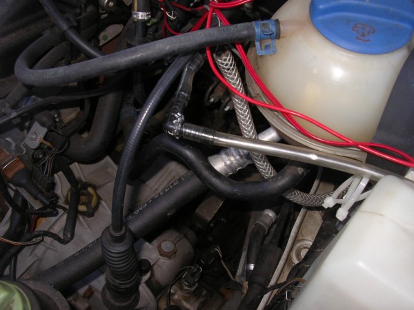
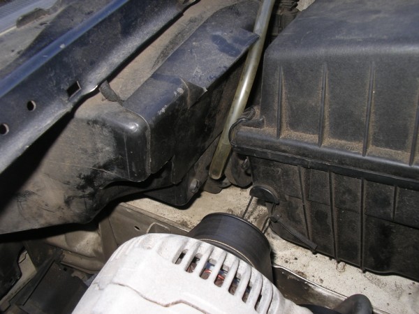
I also decided to feed the gas into the air intake before the air filter. At the point where the tube goes into the air filter box is an elbow with another piece of tubing which takes the HHOO further into the box. The air filter will also serve to act as a "scrubber" for contaminants. The air filter is above the gas tube so any liquid which may be harmful to the engine will drain off, while the gas proceeds upwards via the air filter to the intake manifold.
I had to close off the gas entry point where I previously fed the gas directly into the intake manifold. I also removed the short section of tubing connected to the brass fitting on the inside of the air intake pipe. I did not make a permanent job of closing this entry point in case I decide to use it again.
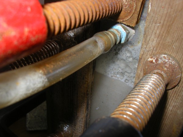
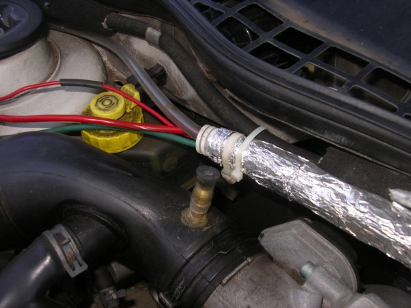
I predict that we will be loaded with more fuel price hikes between now and the end of the 2010 FIFA World Cup, and beyond. These will be accompanied by more electricity price hikes (Eskom's terrorist brother Telkom will probably also climb on the band wagon). The reason for this forecast? The regime will still need a lot more money to pay for the privilege of hosting this world class event. After that the powers that be will continue experiencing shortfalls in all sorts of places as the ruling party's members' personal greed continues to bleed this country dry. End result? Power blackouts and unjustifiable fuel increases. An easy cash cow for the regime is to up the levies on the fuel price. These levies have seldom been used for the intention for which they were instituted, namely for the Road Accident Fund and the building/maintenance of roads. And so we continue to be screwed... (by our "liberators"). I made enquiries regarding the thickness of perspex that I intend using on the ends on my dry cell. I was shown a piece which was 10mm thick and I now believe that I don't need a piece as thick as 16mm (on which I was last quoted). I need to get fresh quotes on this thickness as well as a new order of 316 ss plates. 26 May 2010 We did a round trip to Durban and back of 354,7km today. I ran the electrolyser as it was with no adjustments. It was a reasonably warm day (about 27°c) and so the aircon was on for most of the time. This mileage includes about 100km of town driving. At the start of the journey the ammeter read 17A for a while before climbing up to 21A where it sat until we were well on the way home, then it climbed to 25A. Immediately on our arrival home I checked the system out: Electrolyte temperature: 47°c Amperage: 25A HHOO output: 600ml per minute The terminals on the electrolyser were only slightly warm to the touch. Fuel consumption? Only 13,18km per litre. Although I was expecting something better, considering that I get 11km per litre in town (without the electrolyser) and at least 100km of the 354,7km was town driving, this consumption is not too bad. It would have been far better if I could get around the MAP sensor. At least on this trip my car was not spewing as much carbon monoxide into the atmosphere as what it normally does. I will adjust the concentration of the electrolyte so that the HHOO output is closer to 500ml per minute. With the present setup the intercooler is not effective enough for the kind of trip we did today. I seriously need to find the money now in order to build my dry cell. 27 May 2010 I have re-installed the second scrubber. The lid is now glued on and for extra measure I added a few turns of insulation tape.
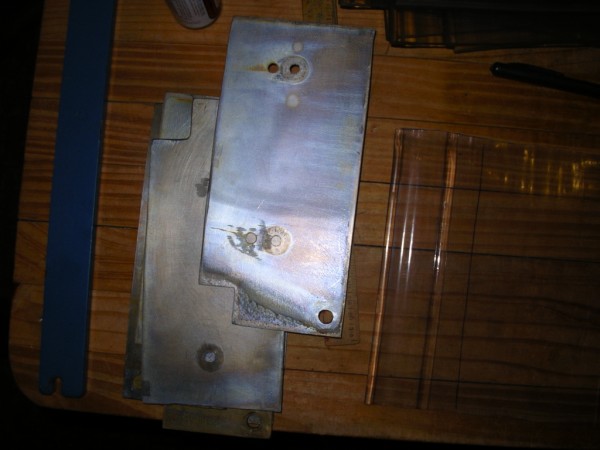
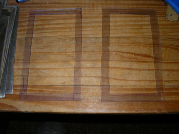
This photo was taken with the electrolyser running, hence the bubbles. Before I re-installed the scrubber I drained 500ml of electrolyte off and replaced it with 500ml ordinary tap water so as to reduce the amp draw. Start-up amperage is now 13,5A. I will run the system like this for the next day or so. I don't know if I'll have the opportunity of running it long enough to find out what the amperage will rise to, we'll see... 28 May 2010 I did some town plus short 80km per hour trips today. Soon after startup the amperage moved from 13,5 to 15A, where it stayed until my return home. I'll continue to run it like this for now. Whether I'll see any gains in economy or not, I'll only know in time. At least in the meantime the exhaust will be spewing less carbon monoxide into the atmosphere. I placed my order for the 316 ss plates and perspex for my new dry cell today. Yay! Here is how I want to build my new dry cell. The SS plates and the insulating spacers are overlayed over the perspex end plates.
The perspex end plate depicted on its own.
The SS plate with the insulating spacer.
I will continue to follow Eddie Batista's principle of HHOO as far as the positive and negative plate configuration is concerned. The positive and negative cables will be soldered onto the relevant plates. I'll ask the engineering firm supplying the plates to do this for me as I don't have the means to silver solder these connections. Here is the schematic of the side view.
I would have liked to use only 12 plates which would have resulted in an 11 cell system, so as to divide the voltage to give 1,25v per cell (the battery puts out 13,8v when the alternator is running). But then I would not have been able to apply the HHOO principle. As a result I am going for a 13 plate, 12 cell system to give effect to the HHOO principle, i.e. +nnnnn-nnnnn+. In this configuration the voltage per cell will only be 1,15v which may be a tad too little. If I find that this is not working as well as anticipated, then I will experiment with a 12 plate, 11 cell system configured for HHO +nnnnnnnnnn- to attain the accepted norm of 1,25v per cell. My striving for 1,25v per cell is as a result of what the boffins on the net have said to be the best for optimal gas production. They say that anything much over this voltage only contributes to the generation of heat. Here is the schematic of how the cell connects with the reservoir. The idea is that the cell is completely flooded with electrolyte. The pressure of the gas will force electrolyte out with the HHOO up to the reservoir. In the reservoir the incoming gas/electrolyte mixture comes in above the level of the electrolyte. The HHOO then vents out to the scrubber while electrolyte flows back to the cell to restore the equilibrium. A self sustaining system...of so iets...
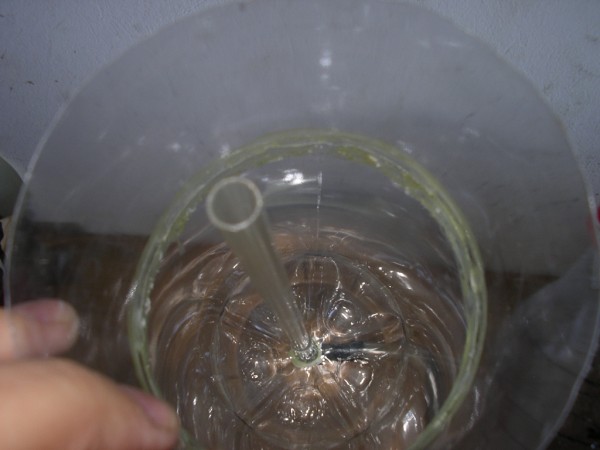
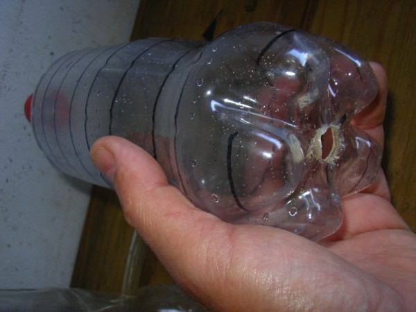
I am not certain whether 2 vents for the HHOO/electrolyte mixture are necessary. There will be an 8mm diameter hole in the top of each plate to allow for the through flow of gas/electrolyte. However, I read in one of the HHO forums that current flows from the negative to the positive. So with my set-up (theoretically) there should be a flow of current from both sides of the middle (negative plate) outwards to the positive plates. My reasoning is that by allowing the gas/electrolyte to vent in the direction of the current flow, then this flow will go naturally from the middle outward. Anghasi... Hopefully I will receive the SS plates as well as the perspex end sections next week. I don't have a problem with the people supplying the perspex - Pauline is on the ball. But I am going to glue my boot to the butts of the guys at the engineering firm where I placed the order for the SS plates. I will also see if they can give it what is called a "brushed" effect, which theoretically should help with gas generation in accordance with the principle of criss-cross sanding. Although there are some who do not believe that this is necessary, others swear by it. So, for once, I will try it too. I have at long last made a better contraption to measure the gas out-put from the cells. The construction is quite simple: I used 2 x 2liter Coke bottles, a 1liter Coke bottle, an 8mm elbow fitting and a short section of 8mm id tubing. I first cut off the top section of the one 2l bottle and then I drilled a hole in the bottom. I then glued the elbow fitting into this hole. I cut the bottom off the other 2l bottle and glued it over the bottom of the first one. There is an 8mm tube over the end of the elbow fitting which exits through a hole in the bottom which has been added. The body or straight section of the second bottle I glued onto the top of the first bottle so as to extend it. I fitted a clear piece of rigid pvc tube over the elbow on the inside (bottom). The 1l bottle I measured out and marked in increments of 100ml.
The rigid pvc tube is fitted to the elbow by way of a short piece of 8mm id tubing.
The hole in the bottom of the 1l bottle into which the rigid tube slides easily.
The 1l bottle inside the contraption, ready for use. The screw cap of the 1l bottle is removed when the contraption is filled with water. The cap is then replaced and the output of the electrolyser is connected to the tube at the base of the contraption. The gas displaces the water inside the 1l bottle and voila the amount of gas generated can be measured!
I tried this contraption and it worked perfectly. At the present electrolyte concentration it measured 100ml per minute at 11A from a cold start. After running the engine and electrolyser for about 10 minutes the output increased to just under 200ml per minute at 13,5A. I added a little KOH and at 15A the system put out 350ml per minute. At this stage the electrolyte temperature is only about 20°c. I am not very convinced that this small amount of gas can make much of a difference, but I will run it at this setting for a while. I think the next step after this will be to play with the gizmo to adjust the signal to the MAP sensor.
|
|
The information presented on this website is for you to look at, learn from, laugh at, or whatever. But if you try anything that you see here it is at your own risk. I will not take responsibility for your stupidity should something go wrong. |
.jpg)