Water Power

Run your car or bakkie on water with a HHO or HHOO generator.
![]()
![]()
![]()
![]()
![]()

You may e-mail me at
john@hydroxypower.co.za with questions, suggestions or if you
can help in any way.
|
Water Power
Run your car or bakkie on water with a HHO or HHOO generator.
|
|
How to build a basic hydrogen-on-demand wet cell. Keep it green with organic Septic Tank and Pit Latrine Treatments
|
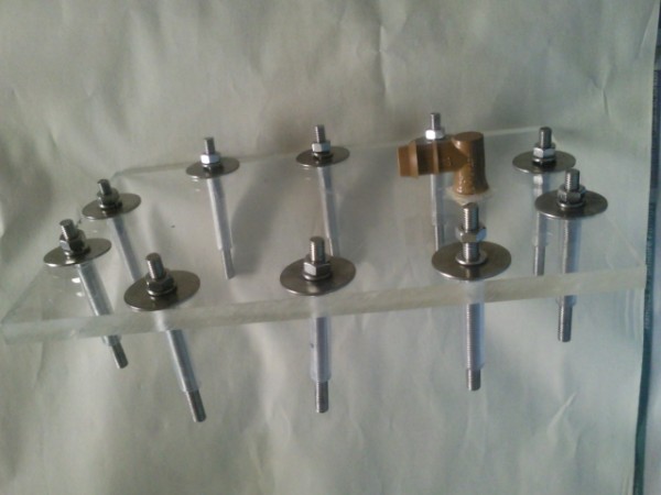
15 April 2011 Sean contacted me again with the following up-date on the PWM: "I would love to show you where we are with the PWM, since I ran into the last obstacle. I have redesigned the entire board, and am doing a variable frequency variable duty cycle using a PIC micro controller. The PWM V2.1 doesn't function efficiently under test conditions, because of the lack of being able to get the correct components. There is only once place to get the matching components and that is from Digikey and the shipping expense is huge. I therefore made another plan and designed a new PWM from scratch. I am confident that this will give us what we are looking for. If we can make a plan, and we can meet twice during the period you are here, I am sure that you will be able to take home a new and shiny tested PWM." Exciting stuff! Thank you Sean! I can't wait to meet him when we go up in a week's time. 17 and 18 April 2011 I stripped and rebuilt my dry cell in preparation for my trip to Gauteng.
At this stage I realised that the connecting cables should already have been bolted to the active plates, so I stripped it all and connected the cables before re-assembling the cell again.
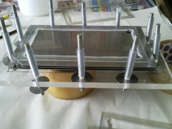
I incorporated a second gas-out fitting at the top of the cell to assist with the free flow of gas.
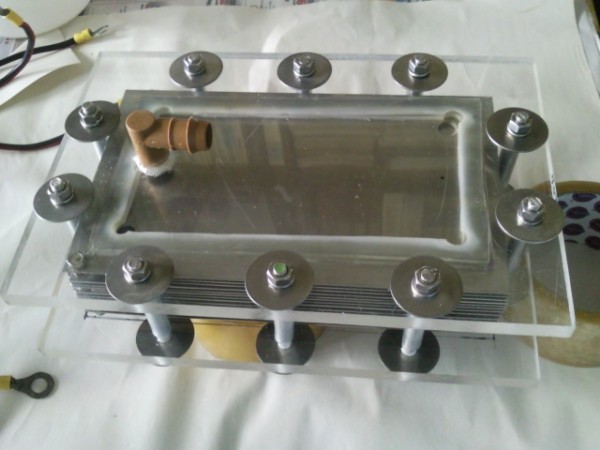
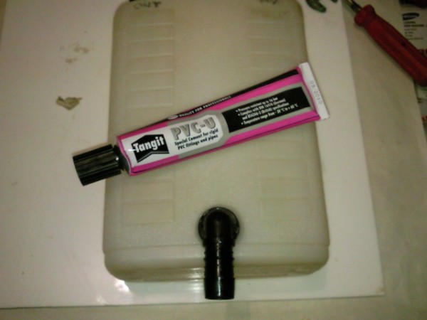
I used this elbow fitting with the threaded end screwed into the electrolyte reservoir. I first tried pvc glue to fix it but it didn't work. I eventually went back to Pratley's putty. This also kept on leaking and I had to redo the putty a number of times before I had a reasonable seal. I am not satisfied with this container so I will keep on looking for something more suitable.
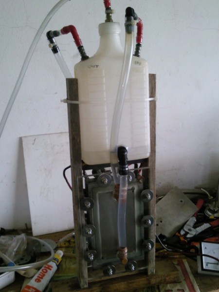
The completed assembly. The gas outlets on either side of the cell, and also the return for the electrolyte from the reservoir to the cell, function very well.
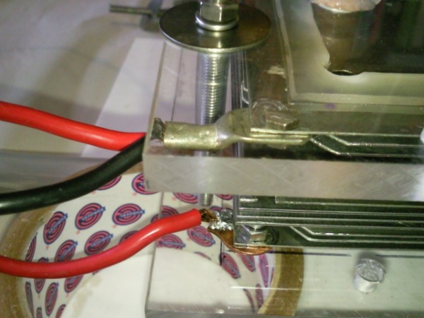
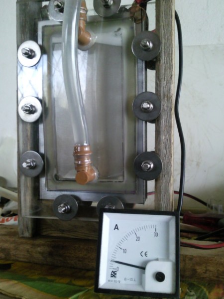
The cell running at just over 3A. I have not measured the output yet as at this amperage it is still insignificant (250ml/minute or less).
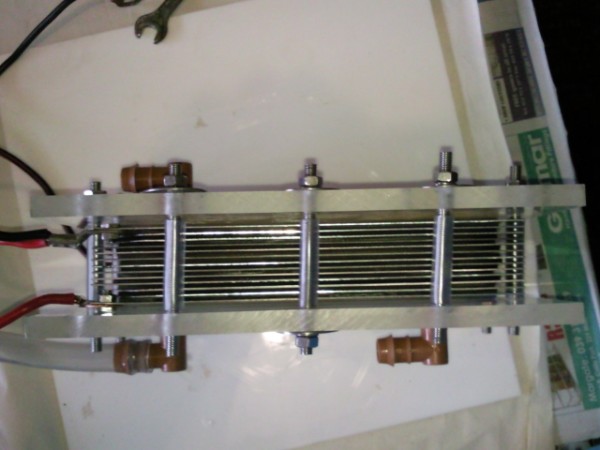
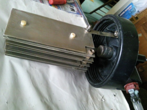
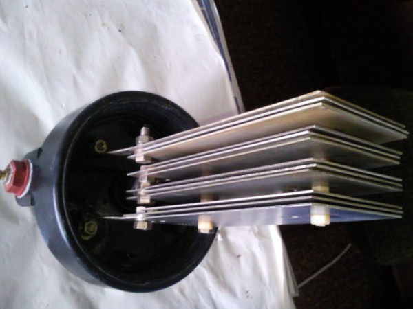
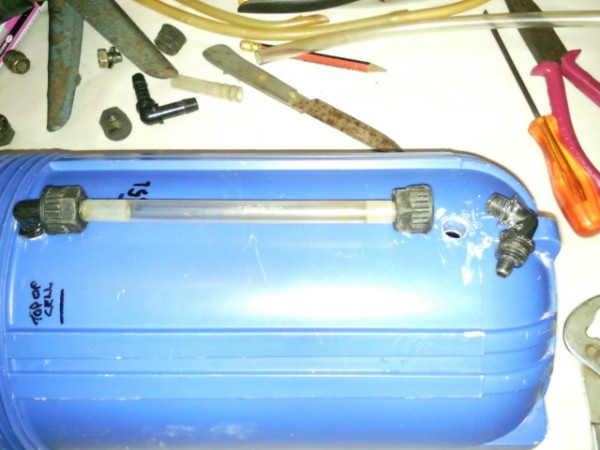
In anticipation of the PWM I decided to resurrect my old wet cell. I stripped and cleaned it before re-assembly.
The putty is where on a previous occasion the terminal heated up and a hole blew (no explosion thankfully!) through the lid.
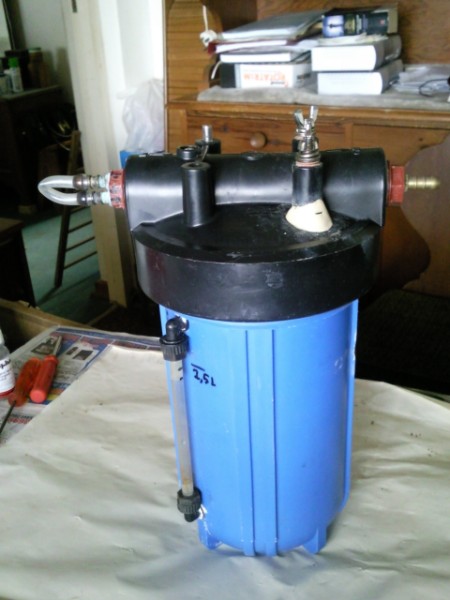
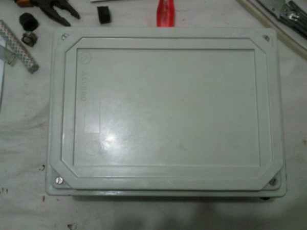
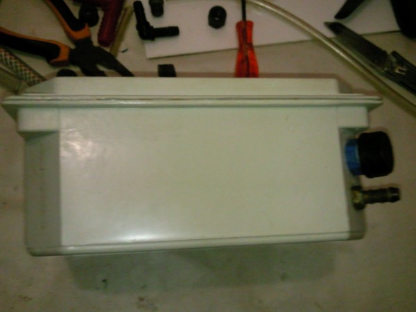
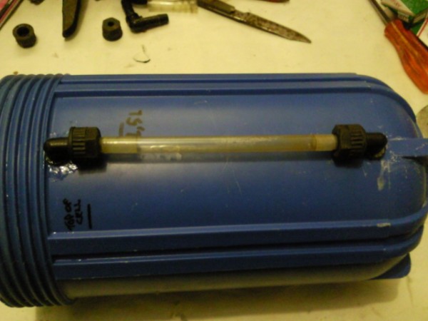
I'm not going to hassle at this stage about a reservoir for the electrolyte for this cell, as it can hold 2,5L. I want to test it at 30A and let it run to see how long it takes for the electrolyte level to drop eg. 10mm. If this occurs too quickly then I know a reservoir will be required. 19 April 2011 I was not happy about the reservoir so I scratched through all my scrapped projects and found a fiberglass box which had previously been destined as a cell housing.
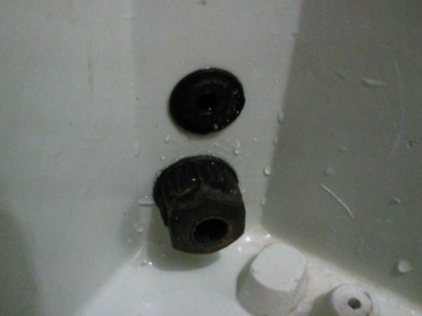
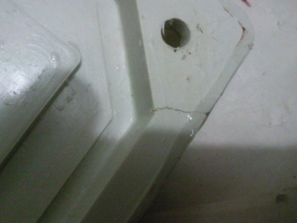
There were already 2 holes drilled through 2 of the opposing corners: this end I used one as the electrolyte-out and the other as a drain plug.
On the inside: the top fitting is where the drain plug sits and the other is for the electrolyte return to the cell.
At the other end the one hole will be for the gas-in and the screw-top is for filling the reservoir.
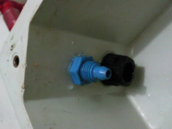
On the inside: the fitting on the left is for the electrolyte refill and the other is for the gas/electrolyte-in.
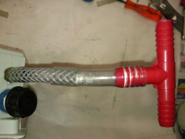
On the gas/electrolyte-in fitting I fitted the connections for 2 inlets for gas (the dry cell has 2 gas outlets). If I use this reservoir on the wet cell (which I probably will) then I only need to remove the T-piece and the immediate adjoining tube to link it to the wet cell's single gas outlet.
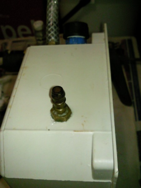
On this end I put the gas-out (to the engine) fitting.
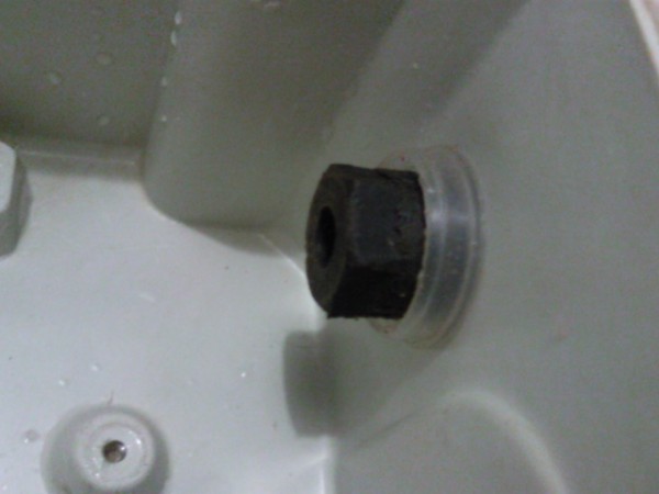
The inside of the container with the gas-out fitting. I made a splash guard from a plastic pill container: I mounted the lid over the brass fitting protruding into the reservoir and boppa'd it vas with a disting fitting.
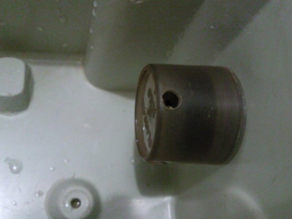
The modified pill container clipped onto it's lid.
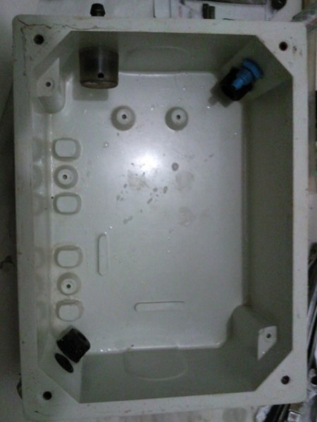
The inside of the reservoir with all the fittings now mounted. The reservoir will be mounted in this upright position. I ran silicon all round the edge of the facing surface and screwed the lid on.
I saw that there was a leak from the bottom fitting of the sight tube. I stripped it and epoxied it back in place.
I also epoxied the top fitting for justin.
Tomorrow I will see how I can now mount the reservoir with the dry cell and what I need to do to mount it with the wet cell if I swap-over. 20 April 2011 I tried to mount the new reservoir above the dry cell, in the place of the previous "fridge bottle" reservoir - and it's not working. It all sits awkwardly and when I filled the reservoir and cell with ordinary tap water to see if there were any leaks, I found water leaking from a small crack in the lid of the reservoir. I used Pratley's to seal it.
A view from the inside.
I will have to build a purpose-made frame to hold the dry cell and the reservoir. I want to make it multifunctional so that I can inter-change the dry cell with the wet cell. Not ideal as the more I fiddle with the epoxied fittings on the dry cell the greater the chance that one of these will loosen and leak. I don't have much choice at the moment as I lack the funds to do it properly. 24 April 2011 Today was a great day, I finally met Sean who is building my PWM for me. He certainly knows electronics and I had a hard time keeping up with him. With Sean's PWM it is also possible to dial up the frequency desired. He has based the frequency range that can be selected on the information that Zero (from Zero Fossil Fuels) bases his PWM on. Sean has incorporated a LCD which will display the frequency, the amperage, and also the temperature of the electrolyte. To me this last innovation is a big bonus! We briefly rigged-up my previous cell (the wet cell) to demonstrate to Sean how the system is set-up for my car. With this information he is now going to complete the PWM. Hopefully it will only be a few days and then he'll have it ready. With the test the amount of electrolyte that I mixed in drew 26A when the engine was running. I didn't have any means to measure the gas output, but judging from the stream of bubbles it wasn't too bad. At the time I said to Sean that it was in the region of 800 - 900ml/minute. Thinking back now I recon in was probably somewhat more, and definitely higher than 1l/minute. The wet cell holds 2,5L of electrolyte (at this level the plate connections are not submerged) and my thinking now is that with the PWM I will no longer need a reservoir for circulating or storing additional electrolyte. This would certainly cancel out a lot of problems! I measured the fuel consumption on the trip up here, including the journey today to get to Sean's house (about 45 minutes x 2 return highway driving from where we are staying with our daughter). The first leg of the journey from Port Shepstone to Harrismith was bad, the consumption being only 10,2km/l. The second leg which included today's trip was better at 13,8km/, but nowhere near what I usually get, Why? I think it may have something to do with the major service that I took my car in for just before we came here. Notwithstanding the fact that I still have not resolved the issue with the MAP sensor, I would like to re-install the cell with the PWM and set it to run at 30A for the time that I am here in Gauteng. Depending on the PWM I would also like to push the amperage higher to see how the whole system handles it, and also to see how much gas will be put out! I will still be doing plenty of highway driving before we return home (you can't really go anywhere here without traveling on a highway). I would like to see the response of the MAP with a constant gas flow of 1l/minute plus. This will also let me gauge how much electrolyte is consumed when the cell runs at a constant high amperage. Last week when I started preparing for the trip, packing the bits and pieces in anticipation of running the cells with the PWM, I realised that I had run out of Potassium Hydroxide (KOH) for the electrolyte. The source via whom I usually order it from takes about 2 weeks or more to get it from Durban, which time I did not have. They are also very expensive at R45/kg (the price I last paid about 18 months ago). I decided to try another company on the off-chance that they would sell to the public. Not only did they have KOH, but they sold it to me at less than R20/kg! So I now have more than enough with me to do all manner of trials. Exciting Stuff! I cannot wait to continue this epic journey! 30 April 2011 I have met Sean a few times now and a prototype of his PWM is installed in my car. There are a few bits which are not yet fully functional so the only reading on the LED display that I can rely on is the % duty cycle. Sean is expecting to get the final version of his redesigned pc board next week. When the final (?) PWM is completed I will post photos. My first tests some days ago gave the following results: Test period Duty cycle Temp of electrolyte Ambient temp Temp of terminals 30 minutes 5% 17degC 17degC + too hot to touch, neg hot The gas output measured 1 liter per minute. My DC ammeter was connected in-line with the PWM so the reading of 27A was probably not correct, but it should be a close indication. The nut on the positive terminal on the inside of the lid was ever so slightly loose, which accounts for the terminals heating up. I tightened the nuts up and ran a second test. Test period Duty cycle Temp of electrolyte Ambient temp Temp of terminals 30 minutes 50% 17degC 17degC + not too hot (touchable), neg warm The gas output measured 1,3 liter per minute. I added another nut on each terminal bolt (on the outside of the lid) to ensure a good lock before running a third test: Test period Duty cycle Temp of electrolyte Ambient temp Temp of terminals 30 minutes 100% 17degC 17degC + not too hot (touchable), neg warm The gas output measured 1,4 liter per minute. These results showed that the PWM was doing what Sean designed it for: to control the duty cycle so that the amperage does not run away and so that there is no heat build-up. Bakgat! My initial road test tells me that at the rate that the fuel gauge dropped the MAP sensor was doing what it is programmed to do, which is to read the air/fuel mixture as too lean and then run a rich mixture, therefore no gains. I then disconnected the negative connection to the battery for about an hour to reset or wipeout the engine management system memory. I will continue to run the electrolyser over the next few days to see what the results are. Unfortunately I do not have enough money now to fill up the tank to make a proper determination.
|
|
The information presented on this website is for you to look at, learn from, laugh at, or whatever. But if you try anything that you see here it is at your own risk. I will not take responsibility for your stupidity should something go wrong. |