Water Power

Run your car or bakkie on water with a HHO or HHOO generator.
![]()
![]()
![]()
![]()
![]()

You may e-mail me at
john@hydroxypower.co.za with questions, suggestions or if you
can help in any way.
|
Water Power
Run your car or bakkie on water with a HHO or HHOO generator.
|
|
How to build a basic hydrogen-on-demand wet cell. Keep it green with organic Septic Tank and Pit Latrine Treatments
|
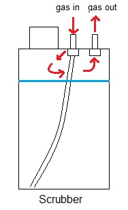
6 June 2011 I filled up today after a trip last week from Toti to Port Shepstone (about 90km) and about 228km subsequent town driving: consumption was only 9,6km/l! This is a clear indication that the oxygen sensor is working against the HHOO. However, on a few occasions during this measured period of 318km I saw that there was no gas bubbling in the scrubber. I found on each occasion that one of the clear plastic tubes connecting to either the brass barbed fitting on the electrolyser or on the scrubber was not sealing properly. As the electrolyser heated up or as the tubes to the scrubber heated up in the engine compartment, then the tubing would expand enough to allow the gas to escape. Although these would feel tight on the fitting, they were loose enough to make a gap. Lesson learnt! So I fastened all the clear plastic tubing on the barbed fittings with cable ties. I assume that the hydroxy ran long anyway enough to influence the consumption, hence the lousy figure. Let's see what difference this now might make with the hydroxy pumping full-time. I also had issues once or twice with the terminal connectors on either the electrolyser or the PWM heating up. In every case it was as a result of the nuts and wing nuts being slightly loose. I have made sure that all these connections are now securely fastened and with spring washers. There is a reasonable breeze from the cooling fan on the PWM which blows around the electrolyser. I decided to harness this for additional cooling and so I added 2 cooling fins onto each terminal on the electrolyser. With the PWM they normally run warm, but now they remain fairly cool. Unfortunately my camera has packed up and my cell is in for repairs, so I have no means of taking any photos at the moment. 8 June 2011 Today I checked the scrubber again just to make sure that gas was coming through from the electrolyser. With everything running there was no bubbling action at all. There was gas coming out of the pipe coming from the electrolyser, and there was gas going into the air intake - but no evidence of bubbling! I found that the fitting on the gas-in side of the scrubber was leaking on the inside of the scrubber container, effectively bypassing the tube which forces the gas to bubble through the water.
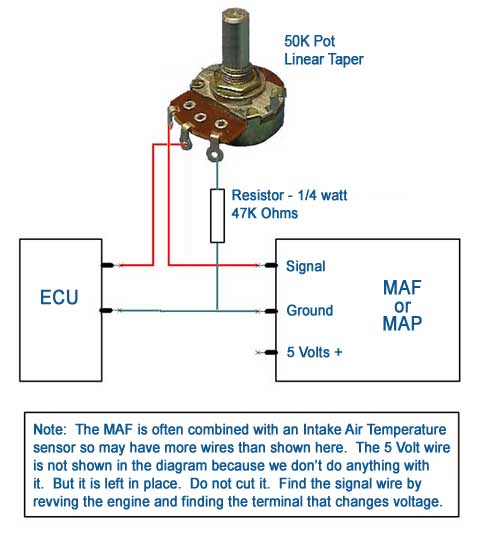
I made a tool out of some spring steel wire to hold the plastic "nut" on the inside of the container so that I could tighten the brass barbed/threaded fitting properly. This sealed the leak - problem sorted! I asked a VW technician today about the oxygen sensor/s on my particular model. He told me that this model (VW Polo 1.6i 2000) did not come out with any. Now, depending on the weather and who you speak to - I have received a different answer from a number of VW technicians! I jacked the car up as high as what my trolley jack would allow and had a good boogers from underneath. Nothing that I could see. So, if there is no oxygen sensor then it means that I am back to fighting with the MAP sensor! The question is: how do I get around this bugger? HELP!!! 9 June 2011 I spoke to a VW "fundi" today and he told me that the MAP has no influence on the throttle. If there is more oxygen coming into the manifold he recons that it doesn't cause more fuel to be pumped into the engine. We put the car on the dyno and it came up with some interesting information: 1. When the electrolyser is on the exhaust belts out a slightly higher percentage of carbon dioxide! Huh? 2. The power also drops (slightly). So what happened to "the MAP does not read the additional oxygen and add more fuel"? Because a too rich condition (in my opinion) is the only reason why the dyno readings all read negatively! 10 - 12 June 2011 I did a round trip of 1 539,1km to Bloemfontein and back. On the way up I ran the electrolyser for the first 3,5 hours. By then the temperature in the electrolyser had gone up to 40 deg C. Although the amperage stayed at 20A the whole time I switched the electrolyser off as I was worried that the electrolyte might start to boil. I ran the electrolyser twice more after that once the temperature of the electrolyte had cooled down to 30 deg C. Every time I stopped for a break I checked the temps of the terminals on the electrolyser and they both stayed remarkably cool (only slightly warm). I spoke to Sean after my arrival in Bloem and he reminded me that water only boils at 100 deg and that I should have let the electrolyser run until the system reaches whatever it's optimal operating temperature is, and stabilises there. Today on the way home I decided to let the electroliser run and see where the temperature went to. We left Bloem at 7.30am with the ambient temperature at 7 deg C. The start-up amperage was 16A, which soon shifted up to 20A (duty cycle 47 deg). After 4,5 hours on the road the temp was up to 50 deg C and still steady at 20A. After another hour the temperature was up to 57 deg C. The whole time the car ran beautifully. There was no indication of any power loss - in fact I had to concentrate hard on keeping to the speed limit! After 6,5 hours of running I noticed that the LED read-out was showing the amperage as 0,5A. the temperature was now 55 deg C, the other readings still normal. Obviously something was wrong! I switched the power to the PWM off and soon after that I made a stop to drop my daughter off at her flat in Durban. There was no gas pushing through the scrubber which confirmed the sad fact that the PWM had died. I saw that the terminal on the side of the PWM, which fed power to the negative terminal on the electrolyser, had obviously run hot as the plastic box had melted in that area and the bolt to which the cable was attached had sagged from it's original position! I checked the wingnut and it was ever-so-slightly loose. I will open the box up tomorrow and see if I can see anything obvious. If there are no red flags directing me to an easy repair then it will just have to wait for the next time I get up to Gauteng and see Sean. He tells me that he is already making progress with PWM version II, so I'll pass on this sorry tale to him so that he can make whatever adjustments or changes as he sees necessary so that this problem can be avoided in the next model. I haven't got any fuel economy figures with the PWM running all the time. In the stretch from home up to Bethlehem the PWM only ran twice. The first time for 3,5 hours and then for about 30 minutes, before I switched it off again. In this run I got 13,033 km/l. From there to Bloem (where the car stood until our return) and then back to Senekal today, where I filled up again, I managed 12,92 km/l. In this run the PWM was off from Bethlehem until just before Bloem, and after that it ran again only from Bloem to Senekal on that tank. The stretch from Senekal to where the PWM stopped working has not been measured as I continued driving home from there without filling up again (purely because I just didn't have enough money). I will continue to investigate the MAP sensor issue to see if I can get to the truth. My conclusions from this trip: the PWM works fantastically well, as the amperage remains the same irrespective of the rising electrolyte temperature. Eddie Batista and Bryan Martin both believed in having at least 3,5 liters or more electrolyte in the cell. I believe that this would go a long way in stabilising the temperature in the cell. The temperature after 5,5 hours of operating at 20A, with only about 2 liters of electrolyte, was only 57 deg C. I think that this is not too shabby, and that another few liters would make all the difference. I want to look at putting the cell into the same type of fibreglass housing which I used before as an intercooler. If I remember correctly it can hold a total of about 6,5 liters. I also want to mount the PWM in a fibreglass box so that there won't be any consequences for the housing if there are heating issues. Right now I'm moeg and I need to hit the sack. 15 June 2011 I discussed the non-working PWM problem with Sean and he says he knows which component popped and why. He has almost completed the next version of the PWM which he says he will be shipping to me soon - as it seems that it might be a few weeks before I will have the opportunity to go back to Gauteng. In our many phone and Skype discussions we have considered many improvements to both the cell, the PWM and generally how everything connects together. The cell lost 250ml of electrolyte on the 1 539,1km round trip. I stripped the cell and found that the connection on the positive plates was slightly loose and that the nut and surrounding area was a dark brown, almost black from the heat. This would account for the temperature of the electrolyte rising steadily. It goes to show that a person can never be too careful about tightening everything up properly. I dug out the intercooler that I built some time back with the idea of using the fibreglass housing for a cell housing. The box is by ABB, a UT4-D deep screw lid box (that's off the label). This box is working well as a cell housing, and although there are one or two things I will do differently with the next one, I am quite pleased with the end result. I filled the cell with 3,8 liters electrolyte and all the power connections are below this level. The plates are mounted horizontally, the way that Brian Martin advocates for maximum production. The plates rest on the bottom of the housing on a rectangular piece of insulation cut out from those strips which are used as insulating curtains in front of cold rooms, to protect the fibreglass bottom. There is therefore no stress on any of the connections to the cell. Unfortunately my cell phone is in for repairs (again!) - and that is the only camera that I have, so I can't show any photos at the moment of what I'm doing. I mounted the cell in the car without the PWM. I connected my ammeter and mounted it on the consol. I will run the cell initially with a start-up amperage of 20A to see how quickly the temperatures pick up. Although I do not have a temperature sensor on the cell, the rising amperage will indicate the increasing temperature. I ran the cell for a few minutes and at start-up at 20A it produces slightly more than 800ml per minute. What is interesting is that this seems to proves Brian right. At the same amperage the cell previously produced only 750ml per minute when it was mounted vertically. Having said that, there is more plate area in the electrolyte with a horizontal mount which automatically lends itself to greater production as a result of the greater hydroxy generating surface. My initial runs with the new cell will be all short local trips, which should give me some indication how quickly the temps ramp up. If it climbs too quickly, then I will decrease the concentration of the electrolyte so that the start-up amperage is 15A and test it from there. The idea is to see how long the new cell will take to heat up to a point where it is generating too much vapour. This will then determine the safe running time before the cell must be switched off for it to cool down. This might be "limp" mode, but at least it is better than feeding no hydroxy to the engine at all. Last night I did a quick google for MAP sensor enhancers, or MAP "fixes". The information available clearly indicates that irrespective of the vehicle or whether the car has a MAP or MAF sensor, these sensors do in fact directly influence the engine management system with regards to adjusting the fuel mixture. It is scary to think that all our local VW "fundis" think otherwise! I want to change the relay and the circuit breaker, both which are presently 30A, to 60/70A. I also want to replace the present power cables with silicone leads which can handle a higher amperage. Sean's PWM can handle at least 70A continuous (if my memory serves me correctly) and it would be interesting to crank it to say 50A just for moz. I can't wait for my new PWM! 16 June 2011 I have been doing some more research on MAP/MAF enhancers and I'm convinced (hope springs eternal!) that there is a simple solution to the MAP problem. I rediscovered a simple circuit that I previously tried - which I want to give another go. I didn't have the patience when I tried this circuit before, and I don't know if I even had it correctly connected! The document that I took the circuit from also discusses MAP sensors which have more than 3 wires. My MAP has 4 wires so I hope that this one is the fix. I still have the pot and resistor for the simple circuit from my first attempt. The document makes provision for a more advanced circuit which caters for 2 different scenarios: a setting for in-town driving and another one for highway driving. If I can get the first one to work then I might get more ambitious and try the dual set-up, if I think that it is needed. What I like about this document is that no fancy equipment is required for the set-up. This is exactly what I need as I am somewhat technically challenged when it comes to gadgets - and also financially challenged which means I can't afford any fancy gizmos anyway! You can find this document in the Information Archive. I discovered small leaks on the cell where I plugged 2 holes with short sections of threaded rod and a nut on each end. At first I tried to seal them with some silicon but they still leaked. I then added a flat washer (all ss) to the inside of the housing with some silicon and this fixed the problem. I lowered the concentration of electrolyte as an afterthought so that the start-up amperage is 15A, which gives a gas output of just over 600ml per minute. I only put 3,5 liters of electrolyte in this time. Til later... 17 June 2011 I assembled the MAP enhancer according to the simple schematic. I used a resistor just over 100k ohms which is what the document recommends to make the adjusting turns on the pot less sensitive.
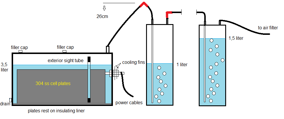
The MAP on my car has 4 wires: I identified the ground/earth. 2 of the wires do not show any change in voltage when the engine is revved. The one where the voltage increases when the accelerator is hoofed is the one which I spliced. I turned the pot until the engine ran rough and then turned it back just until the engine idled smoothly again. I will run it on this setting with the electrolyser running and see how it goes. I hope it is this easy... 18 June 2011 I forgot to mention in yesterday's posting that I included a on/off switch which in the diagram above is connected between the 2 red wires coming from the pot. When the switch is in the off position then the MAP enhancer is functioning. When the switch is on then it bypasses the pot so that the MAP functions per factory standard. Sean is of the opinion that this mod could work and that's good enough for me. The whole issue hinges on whether I do in fact have the signal wire which tells the engine management system to run lean or rich. Time will tell... I did an interesting exercise: I Googled "hydroxypower.co.za" and it turned up some interesting results. My website has been splashed all over a lot of foreign websites, most of them "no spika da inglis". The Yanks mainly refer to Eddie Batista's e-book which is discussed on their HHO forums. On some of the Asian sites they have even posted whole sections out of my story, photos and all! 20 June 2011 I eventually got my cell phone back late this afternoon, hopefully repaired. The one big issue with this phone is that it is my only means of taking photos! I'll take snaps of my latest set-up tomorrow and update. Here is the schematic of how my electrolyser is hooked up now. The gas-out tube from the electrolyser rises almost vertically for 26cm. I did this to prevent electrolyte splashing into the gas-out tube, which can happen when you hit bumps and potholes in the road. In this country this is a big issue considering the shocking state of our country's roads! Although there is a simple splash guard where the gas goes out of the electrolyser, this upright section of hose is an additional safeguard. I have also included another scrubber immediately after the electrolyser with one liter of water. This again is a safeguard to prevent electrolyte and impurities in the gas getting through.
The power terminals sit side-by-side and that's why in the drawing I only show one. Each terminal bolt has 2 thin ss discs as cooling fins for justin. The reason for the 2 filler caps on top of the cell: the holes were already there... I have mounted the cell and the first scrubber nicely out of the way in the boot. It so happened that in order to get everything to fit in snugly, the sight tube is now against the side of the inside of the boot and therefore not clearly visible. But it only takes 2 straps to be unclipped and then the cell can be turned enough to see the electrolyte level. The photos will show it all. 21 June 2011 A view showing how the tubing connects the electrolyser to the first scrubber.
The positive and negative terminal connections with the cooling fins. As an afterthought I also added a cpu fan to blow across the fins which will help with the cooling (until I connect a working PWM again).
The simple MAP enhancer.
The backend of the container for the MAP enhancer showing the bypass switch.
Where the MAP enhancer splices into the loom of the MAP sensor.
With the cold temperatures lately (20deg C and under), and compounded by the wind blowing from the Cape, the start-up amperage has dropped to around 12A. The MAP enhancer sits next to the ammeter on the consol where I can easily reach it while driving.
Two days ago when I started the car, the engine would rev and then die - refusing to idle. the next day it idled, but with bouts of revving. In both cases after the car had run for a while, I switched the engine off and when I restarted it the engine idled normally. I am presuming that this is as a result of the MAP and the engine management system being deurmekaar from the adjusted signal from the enhancer. I'll see how the whole shebang settles down over the next few days. 23 June 2011 I have been going back on my old projects and also re-reading Eddie Batista's e-book. In the past I had a number of issues with some of the cell designs that I tried. Poor gas production, poor quality ss giving off a lot of gunk, the wrong electrolyte and overheating to name but a few. When I analyse the reasons for some of the negative results there are a few things that come to mind: 1. design is critical; 2. type of electrolyte is very important; and 3. a means to control the heat/amperage run-away is of paramount importance. I dug out 2 coil cells that I previously had mixed results with. There are configured + neutral -. When I first tried these cells some time ago I used bicarb as the electrolyte. This cell was a good producer, but gave off some gunk and it heated up very quickly.
The cell below was a very good producer, but it gave off a lot of gunk and also had heat issues. The cell consists of 3 plates 520mm x 120mm in the configuration + n -.
I decided to run these tonight again in ordinary water (no electrolyte). They both produced some gas, the cell with the fine perforations being the better performer. I then added a very small amount of KOH and there was a remarkable increase in gas production. However, there was also a lot of gunk, particularly with the perforated cell. The reason for this was twofold: the cell itself was dirty as I had not cleaned it up at all and secondly the container that I ran the experiment in was a problem. Although I had previously washed this container it still had gunk impregnated into the plastic which would leech out in the process of electrolyses.
I also put a 3 plate cell together, staggered (ala Eddie) in a + - + configuration. I ran it in a clean container with a very small amount of KOH. Very little gas was produced.
This cell ran at very low amps in this solution.
However, when I ran the perforated coil IN THE SAME SOLUTION the results were vastly different!
This cell pulled more amps though.
My conclusions: the perforated coil cell is certainly the better design as it produces significantly more gas that the plate design. If the plate design ran at higher amps then it may be a good producer but then it would have to increase the concentration of the electrolyte in order to achieve this. I suspect that this singular reason (a higher concentration of electrolyte) would result in a significant (and quicker) increase in heat. I want to try the perforated coil at higher amperages and then measure the output to compare it to the 12 plate cell that I am presently running in my car. But in order to do this properly I know that I will have to hook it (the coil cell) up to a PWM so that the heat and amps don't run away. For now though I am just keen to see how much gas it will produce when hooked up to the car as-is. I must say that it has been a rejuvenating experience going back to the old designs! 24 June 2011 I set the perforated coil cell up for mounting in the electrolyser housing. I cut the sheeting to make the connection tabs.
Another view.
I connected the cell up to the car and I first ran it in plain water.
Then I added a small amount of KOH.
I then ran the cell in the electrolyser. Here is the cell connected to the straps inside the lid.
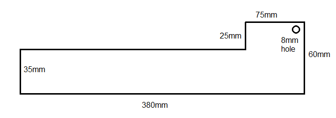
I was a bit disappointed. At 28 amps and it generated 400ml per minute. I mounted the 3 plate cell in the electrolyser and upped the electrolyte concentration quite a bit until it pulled 22 amps. The amount of gas the cell put out wasn't even worth trying to measure. I guess that it might have been about 200ml per minute. I spaced the plates the width of 2 washers, about 3mm which is about what Eddie had in his cell. I'll try it tomorrow with only one washer spacing. I know that the closer spacing will result in better gas production but I don't hold out much hope for this configuration. I will play around with the coils (again), including a design which I previously tried which was a little different to the above one. I will also try them in different combinations of groupings, in series and parallel. I am sure looking forward to the new PWM! 25 June 2011 I have rebuilt some more old projects. These coil cells are smaller and somewhat different to the ones featured above. Each cell consists of 2 perforated ss (poor grade!) plates cut to these dimensions. I cut a slit down the side of a 25mm galvanised water pipe. I put one plate over the other and insert the narrow ends in the slit. I then turned them around the pipe to form the coil.
Pardon the bad photo. Here the 3 cells are connected +-+-+-.
The next 2 photos show how the cells are connected. The strap down this side, which connects to the one side of the bottom cell, connects to one of the power terminals in the lid. I covered this strap with a piece of 10mm id tubing. The strap is far wider than the tubing so it was a mission to coax it over. I did this by soaking the tubing in hot water and pulling it with a long nose pliers, bit by bit!
The opposite side.
Another view.
Looking down the centre.
Showing the connections on both sides.
I will hook this up to the car tomorrow and see how it performs. 26 June 2011 I decided to rather run the cells in my test container to first clean all the gunk off the plates, before I run them in the electrolyser. With no electrolyte the needle on the ammeter didn't move. The power supply puts out 11,39 amps.
Very little gas being produced.
I then added a very small quantity of KOH. A bit of action at 3A. Soon there was gunk showing in the electrolyte.
After about 45 minutes I drained the electrolyte, rinsed the cell and the container with tap water, and I refilled it with clean tap water and a small amount of KOH. The cell drew just over 3A. The shot was taken with the ammeter facing away so it looks like a higher reading. I will run it like this for as long as what the temperature stays cool and the amps under 5.
Twice today my car did the revving thing when I started it. To get the engine to run smoothly I simply switch it off for a few seconds and restart it. I ran the 3 coil cells for 4 hours this afternoon in the second solution of electrolyte. The amperage only went up by one Amp.
The container was slightly warm to the touch and when I put the thermometer in it hardly moved.
There was some gunk in the container, but I'm not sure how much was from the ss and how much came from the container. Even though I scrubbed it out with Handy Andy I could not get rid of the rusty stuff impregnated into the plastic from all the previous trials. So when I got going tonight I rinsed the cell off and put it into the blue housing which is clean and uncontaminated. I set the concentration of electrolyte so that the cell pulls 3A. I will let it run for as long as what it stays under 5A. I have come to the conclusion that there a 3 primary factors which contribute to a cell throwing off gunk: 1. the quality of the material (ss); 2. the type of electrolyte used; and 3. cell design (this includes the voltage and amperage that it runs at). I have been toying with the idea that if the coil cells perform reasonably well (in comparison to my 12 plate cell which I'm running in my car now), then I might order some thin 316 ss and try making coil cells out of this. I think the ss will have to be very thin because I think that it will be a bugger to bend and shape. We'll see.... Update: after running the cell for 1,5 hours it was still at 3A and there was no gunk in the container, save for a very little brown foam on the edge.
But when I switched the power off the gunk showed, albeit not much.
When I powered the cell up again the gunk quickly dissipated. I will continue the process of running the cell, rinsing and running it again in clean electrolyte to see how close it comes to the point of not throwing gunk. 27 June 2011 I ran the cell overnight for 12 hours. The amperage remained at 3A and the temperature was 35 deg C.
I then upped the concentration of electrolyte so that the cell drew 5 amps and ran it for 3 hours.
The temperature went up to 40 deg and the amperage to just over 6A.
I fitted the cell into the housing and connected it up to the circuit in the car. At 17A it gave 500ml/minute. I upped the concentration of electrolyte so that the cell drew 25A, which then gave a gas output of 800ml/minute. Not the best, but not too shabby. I added a bit more KOH to the cell so that when it is connected to the PWM it can run up to 30A. In preparation for testing with the PWM, I also drilled a hole for the temperature sensor.
I tried a spare sensor in the hole to make sure it fitted - nice and snug.
I plugged the gas outlet so that the electrolyte won't spill out when I transport the cell to Jozi when I next go up. I'm hoping that the PWM mkII will then be ready for installation. I certainly would like to try the coil cell running for an extended period at higher amps.
I definitely would like to try making coil cells out of 316ss, but perhaps before that I will probably first redo my present 12 plate cell in 316ss. I only have to find the money now... 28 June 2011 Twice today at start-up the engine would not idle (as it has done before with the MAP sensor enhancer on). A little bit scary as I had to keep on remembering to change gears quickly otherwise the engine would die in mid shift! I also had to touch the accelerator lightly when I stopped to compensate for the lack of idle. It was only when I went to town for the third time that the engine idled normally. As with the times when the engine would repeatedly rev up and return to idle on it's own, I am presuming that the MAP enhancer's influence on the engine management system is responsible for today's problem. The initial indications are that the MAP enhancer is doing it's job. Previously when I ran the electrolyser the economy would often go down as much as to 6km per liter. The present indications are that it is running at 10km/liter plus. I don't have enough money to fill the tank on every occasion so this is just a guestimate. Having said that, the electrolyser has lately been running at 12A as a result of the cooler temperatures. Our daytime temperatures have sometimes been close to or just under 20deg C resulting in the lower amperage. This will result in less gas being produced which may be the partial (or perhaps whole) reason for the reasonable economy. I will measure the gas output tomorrow for the record.
|
|
The information presented on this website is for you to look at, learn from, laugh at, or whatever. But if you try anything that you see here it is at your own risk. I will not take responsibility for your stupidity should something go wrong. |
.jpg)
.jpg)
.jpg)
.jpg)
.jpg)
.jpg)
.jpg)
.jpg)
.jpg)
.jpg)
.jpg)
.jpg)
.jpg)
.jpg)
.jpg)
.jpg)
.jpg)
.jpg)
.jpg)
.jpg)
.jpg)
.jpg)
.jpg)
.jpg)
.jpg)
.jpg)
.jpg)
.jpg)
.jpg)
.jpg)
.jpg)
.jpg)
.jpg)
.jpg)
.jpg)
.jpg)
.jpg)
.jpg)
.jpg)