Water Power

Run your car or bakkie on water with a HHO or HHOO generator.
![]()
![]()
![]()
![]()
![]()

You may e-mail me at
john@hydroxypower.co.za with questions, suggestions or if you
can help in any way.
|
Water Power
Run your car or bakkie on water with a HHO or HHOO generator.
|
|
How to build a basic hydrogen-on-demand wet cell. Keep it green with organic Septic Tank and Pit Latrine Treatments
|
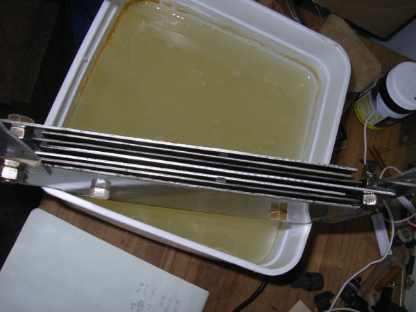
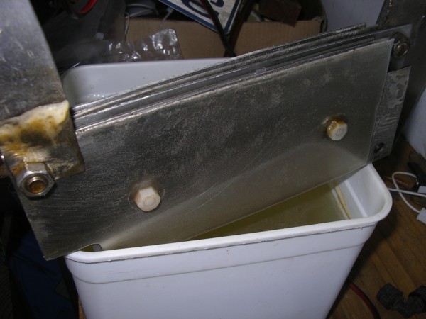
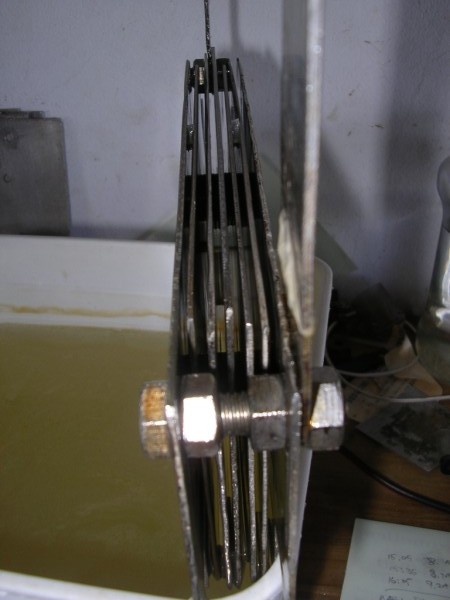
2 February 2010 I drove about 30km today: town with short stretches of 80km p/h. The amperage steadily climbed up to 24A from 19A and because today was relatively cool (only about 28°c) I knew that something was amiss. When I got home I found that the positive terminal on the electrolyser was very hot. The electrolyte was 46°c and the water in the intercooler 42°c. The gas output was only 550ml per minute! What gives? What to do? Easy: check everything! I pulled the electrolyser out and opened it up. This gave me the opportunity to take more photos of my previous repair with the Pratley's putty. Here is a shot of the inside of the lid with the connecting strap to the negative terminal.
Terminals heating up normally indicate that somewhere there is a connection that is a bit loose. I started by checking the nuts holding the connecting straps onto the cell: these turned a mm or so. Next the nuts holding the connecting straps to the lid of the container: both of them also turned a mill or so. Next I checked the connections of the earth and positive cables to the cell: they were both tight. Then the connection of the earth cable to the chassis: the cable was earthed via a spade connecter with which I was not very happy. I replaced it with a round connecter which required the removal of the bolt first. The trip switch connection to the battery and also to the cable going to the electrolyser were also ever so slightly loose. After tightening everything, I replaced 500ml of the electrolyte with plain tap water and re-assembled the ka-tooty. I also made sure that all the tubing for the circulation of the electrolyte and also for the gas was properly connected. With the water in the intercooler down by one degree to 41°c (the electrolyte itself would be much cooler as it had been standing open for a while and also now had 500ml of cool tap water replacing the equivalent amount of warm electrolyte), the output was now 750ml per minute at 22,4A. I'll let the system settle over the next few days and also monitor to see if my efforts have eliminated the terminal heating problem. And it was just the other day that I said that I was glad that I had overcome the problem of terminals heating up! Ja boet... This exercise has taught me to use spring washers on all connections: electrical and mechanical! I have started to assemble the voltage adjuster for the manifold sensor. I superglued 2 different connecter strips together to form one strip. I still need to connect the toggle switch and then mount it in a box. I used a heat sink from an old pc for the voltage regulator.
The auto technician that I spoke to could not give me too much information regarding which wires on the manifold sensor were which. But he did manage to complicate matters for me by telling me that the sensor served 2 purposes: it was a pressure (atmospheric I think) and also an intake manifold temperature sensor. He was kind enough to fax me a schematic that he pulled off their computer. He told me which wire was the earth (the schematic is too blurred and also printed very small, not enough to be readable). The other 3 wires are for the functions of the 2 sensors, but which is which? Anghasi... he did not know. I will have to test the voltages on these 3 wires and hope that they aren't all similar - that I will be able to identify the one operating in the low to 5v range. Ja boet...! If I had the money I would rip this engine out and replace it with a brand new carburetted Jap copy. These Nippon motors are apparently very good (or so I am told) and relatively (for someone else - not me) cheap. These engines have no sensors and you can tell it what to do: it doesn't have any clever brain box deciding for you! Nou ja... 12 February 2010 We went to Durban yesterday to visit the youngest daughter of friends of ours, who was in hospital. I decided not to run the electrolyser as I knew that the sensor would cause the brain box to compensate and this would result in worse consumption than without the electrolyser running. Something interesting: I asked a mechanic recently what he thought of me perhaps removing the fuel injection system off my car's engine and replacing it with a carburettor. I have been in touch with Llew from Australia who sent me instructions on how to do this (apparently it has been done successfully on a number of different cars over there). Well, the reply from the mechanic was that although it may be possible, why would I want to add a carburettor when fuel injection was the most fuel-efficient method? When I mentioned that with the so-called fuel efficient injection system every engine was still blowing ⅔ of the fuel out to the exhaust, he scoffed at me and said that this was nonsense. I did not have the opportunity to ask him why they introduced catalytic converters... I did however mention to him that many years ago there were a number of carburettors that gave 100mpg+ and even some that claimed 300mpg. With this type of fuel efficient technology, why did the big oil companies or the government then buy out or squash and then bury these innovations ... only to replace it with "fuel efficient" fuel injection? He did not have an answer. Ja boet... I finished the assembly of the voltage controller for the MAP or air intake pressure sensor today. Of the 4 wires coming from the sensor one is an earth, which the technician I last spoke to identified as being the brown wire (numbered 1 on the plug). Out of the 3 wires left I had to guess which one might be the one which signals the brain box to mess with the fuel consumption. I first tested the voltage on the wire (engine running) I thought was the most likely one and the multi meter showed 4,9v. I spliced the voltage controller in and whether the switch was on or off I still got a reading of 12 something volts on both sides of the switch. Needless to say the moment the switch was on the engine ran rough and soon cut out. I then went through the same routine with the other 2 wires with the same result. I was busy disassembling the contraption from the sensor when I noticed that I had connected the earth lead from the voltage controller directly to the positive terminal of the battery! Dufus! With renewed heart I re-assembled it all with the earth wire now connected to the negative terminal of the battery (it was easier than trying to get a good earth connection elsewhere!). I had another close look at the diagram that the technician had faxed to me and I eventually decided on a wire which is hopefully the one which is the correct signal wire. The sensor has 2 roles: in the diagram G71 is the pressure sensor and G72 is the intake manifold temperature sensor. The 2 wires out of G71 are the brown which apparently is the earth, and white wire. This last one I spliced into the voltage controller. Reg of verkeerd, this is how I am going to do my first tests. With the voltage controller switch off I started the engine and then I measured the voltage on the white wire. At first it fluctuated rapidly between 1,something up to 9,something volts. Eventually after a few minutes it settled to 2,2v. I switched the voltage controller on and the engine went through its rough running thrombi. I adjusted the multi-turn pot so that the voltage to the sensor was almost the same as the original signal, but the engine still ran a bit unevenly (although less so). From what I understand from the information that I downloaded (regarding the voltage adjuster) the engine must be up to temperature before any adjustments are made to the sensor. Up to this point the engine had only been idling sporadically up to about 2 minutes at a time, so it was far from "running" temperature. I want to find out if anyone local has an exhaust analyser to measure the air/fuel ratio so that I can set the voltage controller for optimum results. Until then, I will just keep on running the electrolyser during runs to town - for the sake of a cleaner engine and more importantly so that the exhaust fumes are less harmful to us, our children and grandchildren, our pets and the environment in general. When I've tidied up the mess of wires under the bonnet I will take some photos and upload them. 24 February 2010 I am now more confused: I spoke to a VW accredited workshop owner today (he is a well qualified mechanic) and he informed me that the manifold sensor (the one and only sensor) did not give any input or influence the engine management system as far as regulating fuel is concerned. Now, without the HHOO generator running I already get good consumption (I'm not greedy, I just want more!). When I run the electrolyser my consumption effectively halves. So, if it is not a sensor ruining the friendship then it can only be one thing: I have to find the right gas curve for this engine. I have gone back to www.fuelsaver-mpg.com/ and notwithstanding what anyone else has said to the contrary, I am willing to try their simple MAF/MAP enhancer. I only had a 10k pot and a 10k resistor at hand which I rigged up to see if it would have any effect. The test to see which is the sensor wire on the MAP sensor is the first one that I've found to return a result confirming the correct one. You do this by revving the car: the wire to the sensor, where the voltage fluctuates and returns to where it was when the engine is at idle, is it. I set the pot to give the least resistance and started the engine. I turned it so that the pot gave a reading of 3,something ohms. the engine ran very slightly rough, so I turned the pot back to 1,8 ohm. Tomorrow I will buy the correct size pot (50k) and resistor (100 - 150k) and these will probably make a difference. Note: the readings that I indicate above may be in k - I don't know. I still need to learn how to properly read my multimeter. Here is the simple assembly. Note the highly professional adjusting tool...
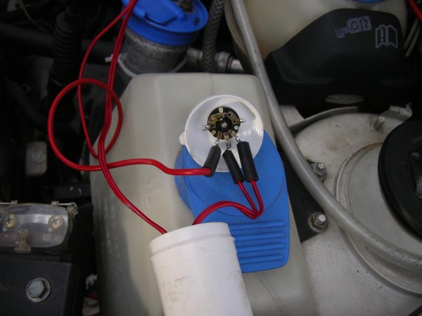
The voltage adjuster connected to the MAP sensor. I made insulating sleeves by pulling the rubberised insulation off another cable.
I put the assembly in a small container which I taped onto another gizmo for the meantime. The engine and the electrolyser were running when I took this photo. If you look carefully you can see the bubbles rising through the water in the scrubber.
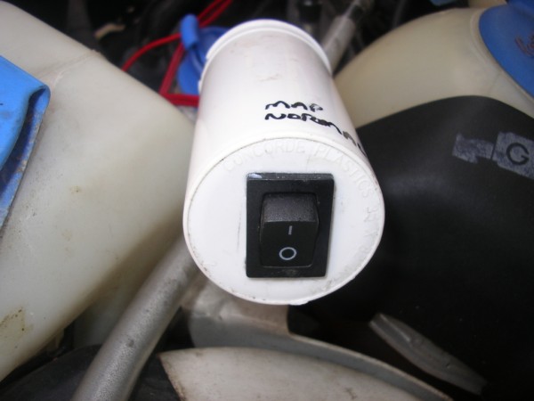
These few bubbles do not look too impressive, but there is no way you can "count" them as I see guys doing on other sites. This photo was taken when the output was at 800ml per minute and the bubbles are actually pouring out in a continuous stream. If you can count the bubbles you are wasting your time with that specific design because then you are producing so little gas that a flea's ears wouldn't pop if it were ignited! Definitely 250ml per minute or less. Either do something else or give up! I suppose its something to do; people who like to count the bubbles probably also like to watch paint dry... I also increased the concentration of electrolyte. The amperage had dropped from its previous level of about 22A and 650ml per minute of gas. It is now back to 22A and the output is up to 800ml per minute. I wish we had guys like those from the fuelsaver-mpg website in South Africa - they would make a killing! I like their positive attitude that they can bypass all the electronic control mechanisms on any car! But I don't think they'll be around for long though, the govmunt ministers who have fingers in the SA oil pie will quickly organise hits on them with their goon squads - either that or they will be shown what our "heroes" can do with tires, some petrol and matches! They will quickly find out that "necklacing" has nothing to do with jewellery! Nou ja... I have been reading the comments by other people about dry cells and I would like to build one and see how that turns out. I think the biggest challenge will be the circulation of the electrolyte to keep it cool. Another challenge will be the gaskets between the plates: what do I use and where do I find it? I might try that insulating material that they hang in front of cold rooms. Some time ago I was (very kindly) given a second hand strip of this by one of the local refrigeration companies. It unfortunately has 2 ridges that run about 30mm from both of the outside edges, so the available width of useable material between the ridges is only 115mm. It is slightly more than 2mm thick, but this is not too consistent over the useable width. Bryan Martin claims that the plates should rather be wider than tall. In his 9 plate design and other designs his plates have all been "lying down" as opposed to mine which "stand up". My choice has been guided by the containers that I use. Whether I do it in a dry cell or a wet cell, I would still like to try his idea of 11 plates "lying down". Why 11? Read Bryan's posts and you will discover why: the voltage from the battery divided between the plates gives you the ideal voltage between plates for keeping the temperature down and also for the best gas production. While I follow-up on the best way to do a dry cell, I want to build a wet cell in the meantime according to the above configuration. I think that I will put it in the same type of container that I am presently using for the intercooler. This, however, brings me back to my age-old problem of how to hold the plate stack together. I need to source nylon/plastic threaded rods!!! Anyway, it has been sometime since I built a new cell so I am looking forward to this one! And... it only costs money! Something else that I also need to acquire soon is a decent inverter to run the basics in my house (lights, tv, computers, etc.) when there is a power failure. And I think these "power outages" are going to become more and more frequent as the world cup gets underway. The govmunt is more concerned about placating the illegal regime in Zimbabwe by giving them and other neighbouring "friends" our power for free (friends: a euphemism for any body who supports the SA regime, which includes the Chinese). But all it takes is...money... Nou ja... 25 February 2010 I sent in an enquiry to a website that advertises that they can help you identify what sensors you have after you provide them with the particulars of your car (my car is a 2000 VW Polo 1,6i). Today I received an answer: Hello John, You have 1 narrow band sensor upstream of your catalytic converter so one of our single narrow band EFIE’s is what would work. We usually still recommend the “Quad Digital EFIE” in these cases because it has the superior digital circuitry and it’s the most flexible if ever used on another vehicle. You can get one in our online store at http://www.fuelsaver-mpg.com/store/.I jacked the car up and looked from underneath, I then took it off the jack and looked from the top - but to no avail. There is no other sensor! I don't know what a catalytic converter looks like, but all I could see were the 2 silencer boxes which have pretty much been a standard fixture on cars for yonks. So... scratch that one. I have an idea that vehicles constructed overseas have probably been subjected to legislation for some time where these converters are compulsory. Therefore the above advice would be true - if I were in America. They would not know that our govmunt doesn't give a rat's se agterwêreld about the environment or the economy. At least it made me make a thorough inspection where I confirmed for myself that there are no other sensors. The next step is to find out whether the MAP sensor does in fact have a say in the fuel being squirted into the engine. So for the next while I will concentrate on this aspect by seeing whether the simple controller can make any impact on the sensor. I am also keeping in mind that the gas curve will also be a factor. Hmmm... Today I was given a 50k pot (second hand, but serviceable), a 120k and a 150k resistor by the owner of a tv and related appliances repair shop, thank you Mark. I assembled the simple MAP enhancer and connected it up with a bypass switch. Here is the original diagram from the above website. My sensor has 4 wires (as the sensor has a dual function).
I added an on/off switch between the 2 signal wires going to the pot. When the switch is off then the voltage controller is in action, when the switch is on then the MAP sensor receives the original signal from the brainbox. I mounted this switch on the underside of the container for no other reason than that it was the only other flat surface available.
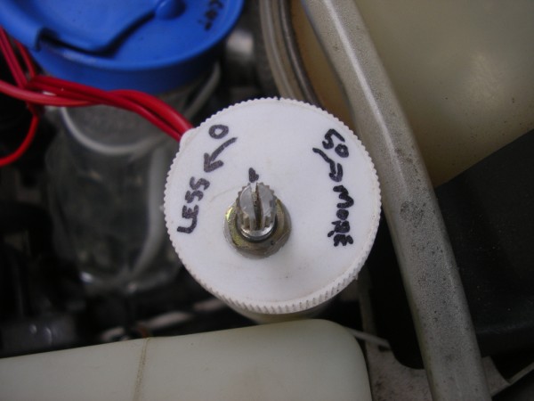
The pot mounted in the lid of the container.
I began by turning the pot anti-clockwise so that there was no resistance i.e. the original signal to the sensor is unaltered. I started the engine and when it settled I turned the pot slowly clockwise. At a point the engine's revs decreased ever so slightly and the motor started running rough. I was ecstatic! At last I was following advice where things happened according to the instructions! I turned the pot back to the point where the engine ran smoothly again and this is where I marked the lid for the record.
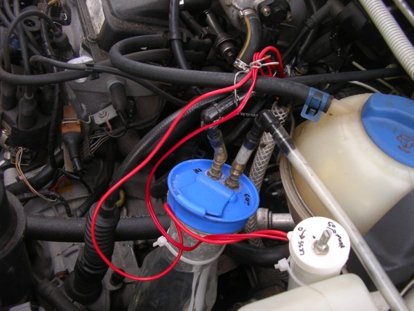
Mounted in the engine compartment. I have subsequently tidied-up the wiring!
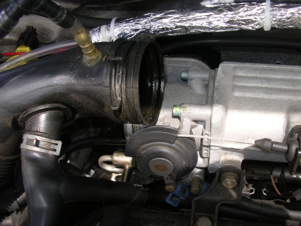
I will run the car on this setting for a while and see what the consumption does. Just for moz I want to take my car in to the garage where the owner told me that there are no other sensors (other than the MAP), so that he can check the carbon emissions. I know him fairly well so hopefully he won't charge me for this service! 26 February 2010 Lately I have been doing a lot of reading on the forum at http://hhoinfo.ning.com/ (which I have now joined). I eat my words (to a certain extent) from one of my previous postings that too little gas is a waste of time. In a way I'm glad that the focus is no longer on massive gas production as it was a few years ago, but rather the emphasis is on efficiency, low current and cells designed to make maximum use of the voltage without heating up/overheating. The buzz word is "sweet spot". I have read it before but forgot about it. This is the point on the gas curve where you get maximum benefit. On the forum I saw something which reminded me about a tweak that I did with my previous car, which I only fitted on my present car this morning, and that is to extend the gas line in the inlet manifold to just before the butterfly. The inlet pipe disconnected from the manifold.
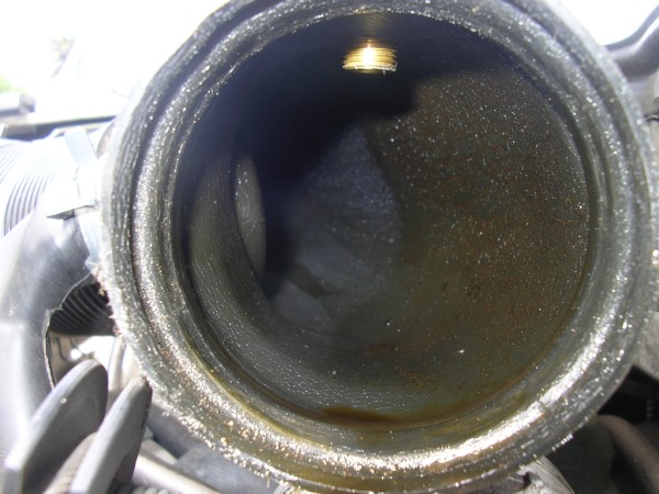
This what it used to look like:
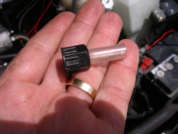
This the new addition. I first fitted this (6mm id tube) and then I pushed an 8mm id tube over it for the extension.
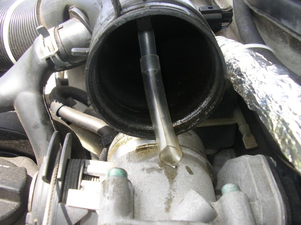
The extension which ends just before the butterfly when the pipe is refitted.
People on the above mentioned forum maintain that this addition alone turned their situation from no gains to impressive results. It is often the small things that count. I did this with my Audi and (also as a result of many other factors) managed a 50% increase in economy. Something else... I thought I'd try out the principle of plates "lying down", i.e. placed horizontally rather than vertically - which is how all my cells have been constructed until now. I took 7 x 304 grade ss plates (I don't have any more of the same size) and rigged them up in a HHOO configuration + n n - n n +. I didn't bother cleaning them before hand so I expected some gunk to be thrown off in the electrolysis process. The first run was for a hour @ 8A and as expected it did produce some gunk. I replaced the electrolyte (KOH in ordinary tap water) and ran it for the next hour @ just over 5A. I adjusted the amperage by decreasing the concentration of electrolyte.
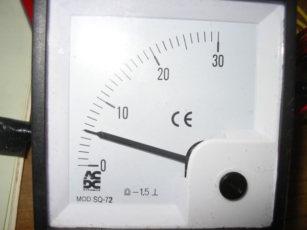
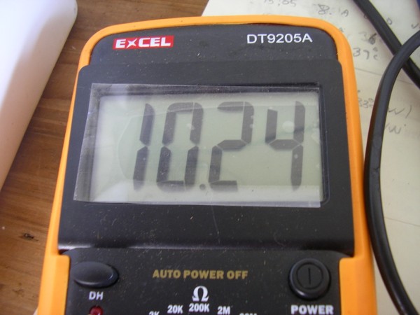
The voltage to the cell.
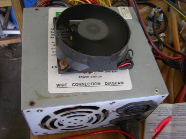
My power supply rigged from a computer power supply. I added the extra fan to assist with the cooling for longer running. Not the best power supply but it is all that I have for now.
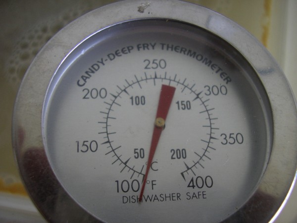
The temperature after a hour. This is a wonderful thermometer that was loitering with intent in the pantry cupboard. My wife never used it and it is ideal for my tests!
Here is a view of the cell from the top. Spacing is with single plastic washers which are 1,6mm thick. The plates are roughly 190mm x 90mm x 1,6mm (or thereabouts) thick.
This cell has now been running for another 2 hours after another change of electrolyte, amperage up from start-up 4,9A to 5,1A. Temperature from cold (± 30°c) up to 38°c. Production of gas is not wonderful, but then I am not yet aiming to amp it up. The voltage to the cell is still 10,24v. There is much less gunk. The voltage across each cell (between the plates) is still too high, the ideal is about 1,2v. From the car battery the cell would be pulling around 13,8v so the voltage across the cells will then definitely be too high. With this voltage more plates will result in greater efficiency. I always believed (as per the boffins on the net) that the voltage is divided between the cells i.e. the number of spaces between all the plates are counted as the cells. Therefore if a cell has 11 plates then it has 10 cells. However, just recently I see some guys count the cells as the number of plates in the cell set-up. Bryan Martin says that the ideal number of plates is therefore 11. This will result in 1,25v per cell (plate). If the cell is counted as the number of spaces between the plates, then @ 13,8v 11 plates would be too few, as the voltage across each cell would be 1,38v. In this case 12 plates would be required to result in 1,25v per cell. I have made enquiries as to the cost of 12 plates of 316 grade: 100mm height x 180mm width x 0,9mm alternately 1,2mm thickness Hopefully I'll hear on Monday what the damage is, now I just need to find the funds! This time I will not ask them to cut or drill the plates, I can do a better job with a hacksaw and a good ss bit! Almost disaster! Tonight we went to a Church meeting, the electrolyser and the MAP enhancer were on. As soon as I floored the accelerator to pass another car going from a 60kmph to an 80kmph zone, the revs suddenly shot up and the car really accelerated! I tried to hoof the pedal to bring it down but this made no difference. My first though was that the mods to the MAP sensor had made it bossies! I rode the brake until I could pull off. I switched the MAP enhancer off and started the car again. Again the revs shot up! What gives? I rode with extreme caution to our destination which thankfully was not too far. On arrival I asked my Office Brother for a pair of pliers so that I could disconnect the cable to the negative terminal of the battery. I thought that with the mods off the brainbox needed time to reset and maybe this would resolve the problem. However, when I opened the bonnet I first decided to advance the throttle by hand to see if it was perhaps sticking. As I turned the throttle thingy I noticed that the gas-in brass fitting just before the inlet manifold (to which I had fitted the extension tube to this afternoon) moved in sinc! Immediately I twigged that somehow when the butterfly valve was wide open (full throttle) it snagged the tube and, well, it made marakas! I pulled the pipe off the intake manifold and removed the extension tube. Problem thankfully solved. I will refit the tube tomorrow after shortening it enough so that at full throttle it won't interfere with the butterfly valve again. I am grateful that it was a mechanical rather than an electronic problem. If you have a problem, use a hammer. If that doesn't fix it then it was an electrical problem! When I started the car for our return home, I happened to glance down at the ammeter to see what the current draw was and... no ammeter! Immediately I remembered that I had removed it to monitor the new cell set-up mentioned earlier on, which I had running in the garage at home. What a dufus! I had forgotten to connect the 2 cables together which meant that the electrolyser had no power and was therefore not running! This, however, did show me that I had to correct something else, this being the led which I had rigged to indicate when there was no power to the cell. With the ammeter missing and the connecting cables not joined together, it was still showing power to the cell! So... everything happens for a reason... Much work tomorrow before I go to town, so... 'till later... |
|
The information presented on this website is for you to look at, learn from, laugh at, or whatever. But if you try anything that you see here it is at your own risk. I will not take responsibility for your stupidity should something go wrong. |
.jpg)
.jpg)
.jpg)
.jpg)
.jpg)
.jpg)